

- Joined
- Jun 24, 2010
- Messages
- 5,705
- Points
- 113
Ok so I got another batch of Flexmod P3's in today. I have had a few questions on how I set it up in my Frankenstein unit so I thought I would just make a thread.
Also if you would like to see more of my reviews and tutorials please visit my compilation page.
http://laserpointerforums.com/f51/d...difications-compilation-53944.html#post759223
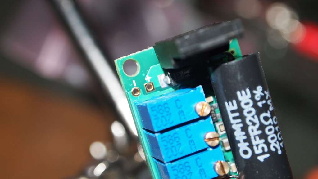
Here is the specs and the module.
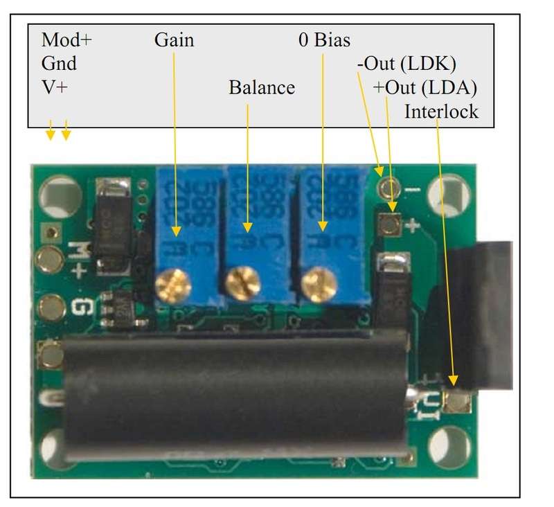
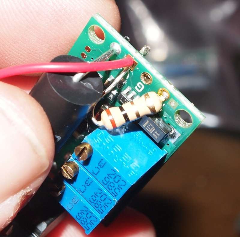
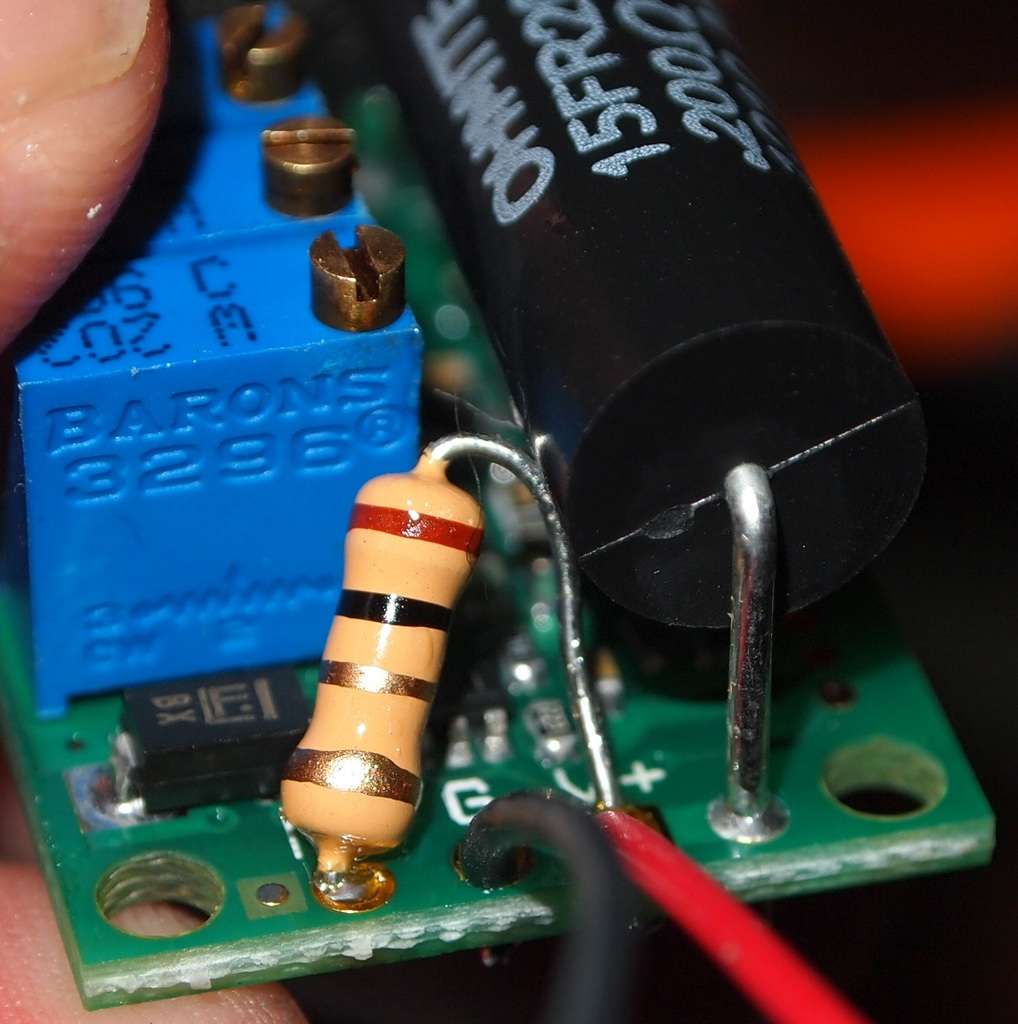
You neet to get a 1.5 K Ohm 1/2 Watt resistor which will be used to bridge the V+ and the M+. The M+ is the modulation input that can be used to adjust the current while in use. We will not be needing to adjust it in this manner so we will use the 1.5 K Ohm 1/2 Watt resistor to wire it in an always on full power mode.
Please disregard the actual resistor shown in the tutorial. I accidentally used a 1 Ohm resistor but the placement is the same.
Here is some info Jayrob got from drlava when developing his Mag kit.
Put the resistor in the holes and manipulate it into the position you want it to be.
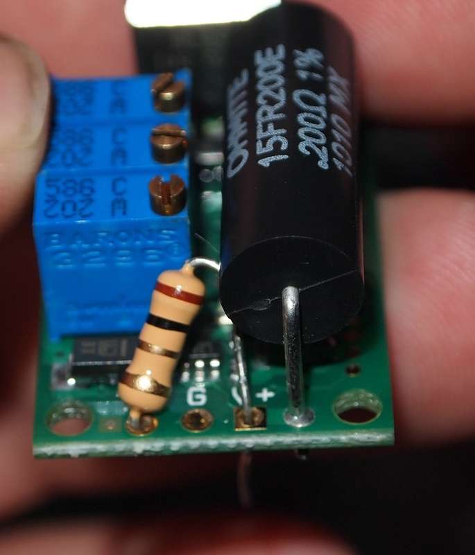
Clip the resistor wire for the in the M+ hole. Then solder it in place.
Now get some wire out. I like to use the extremely flexible and burn resistant Flaminpryo wire.
Next shove the positive wire in the V+ hole along with the resistor already in place.
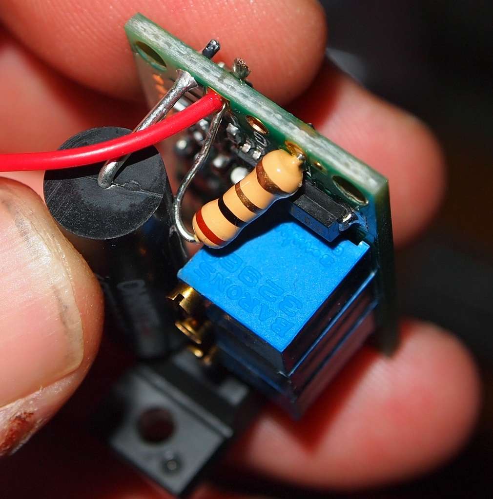
Clip the wires flush and solder them in place.
Add a negative wire in the G hole and solder it in place.
Your Input wires are done. And it should look like this.
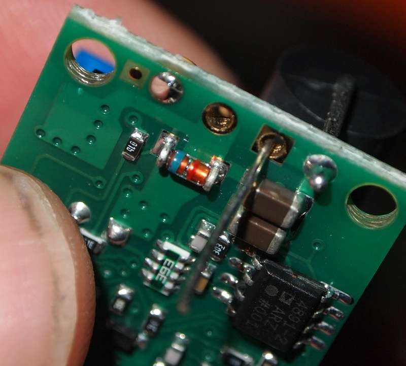
The interlock is a safety feature that can allow the user to cut off the laser. It can be hooked up to an external switch in labbys but since I am using a handheld host I will wire it to be on all the time.
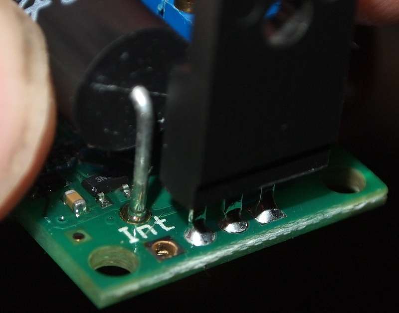
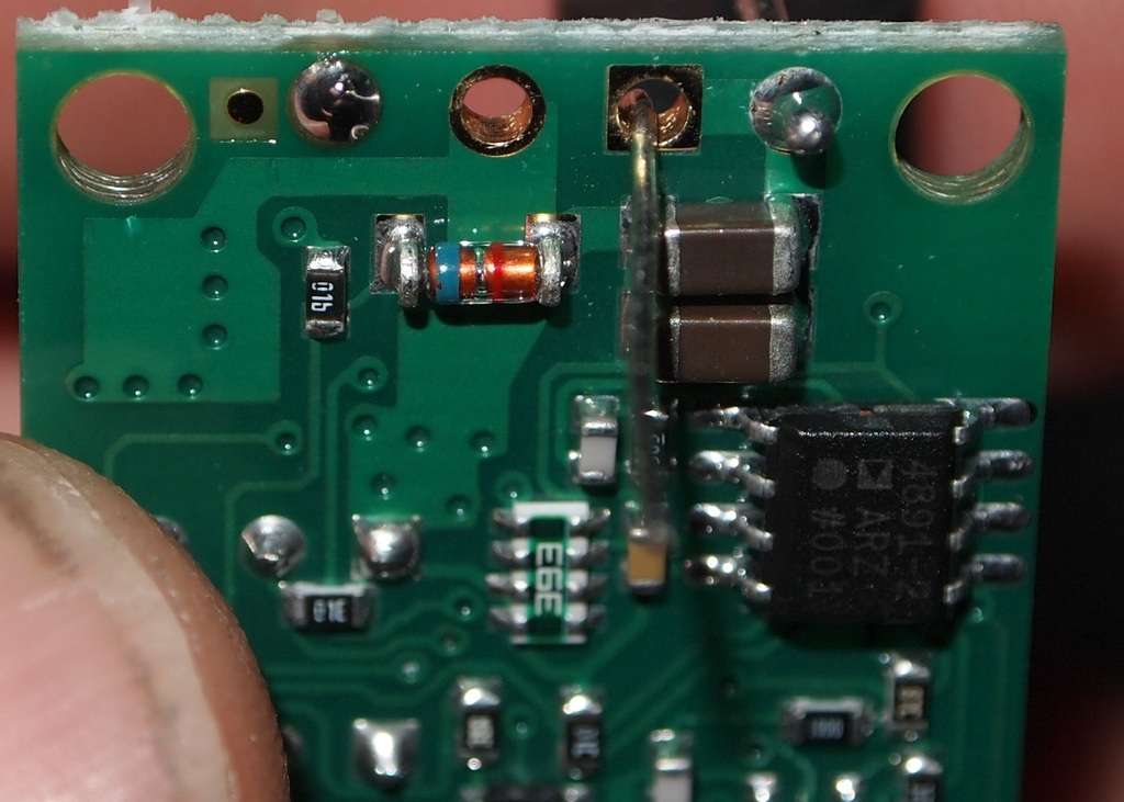
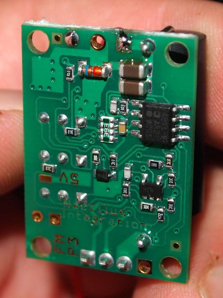
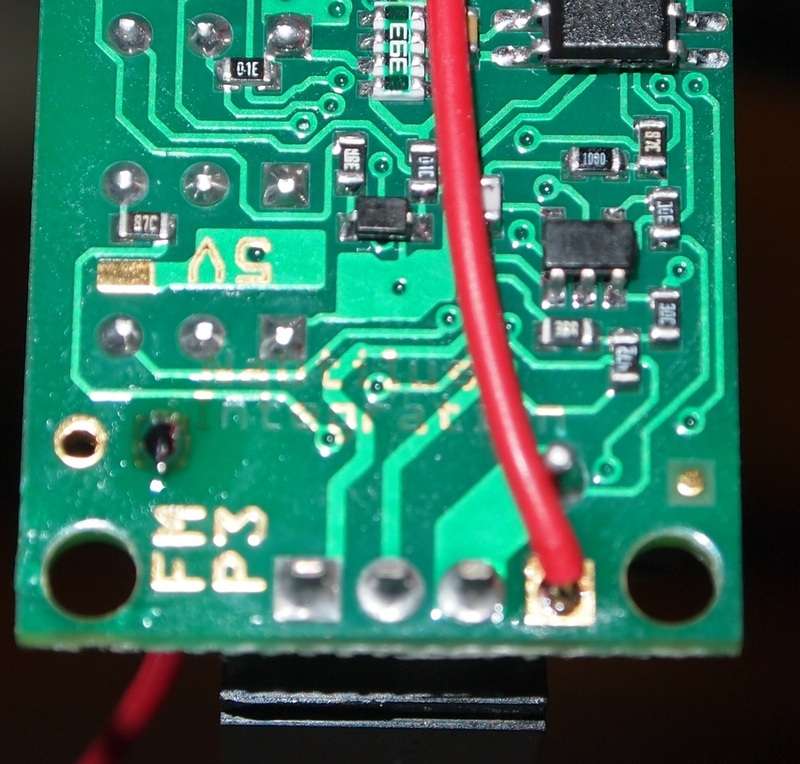
Here is where the hole is for the interlock on the back.
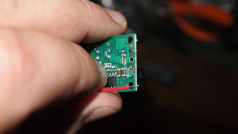
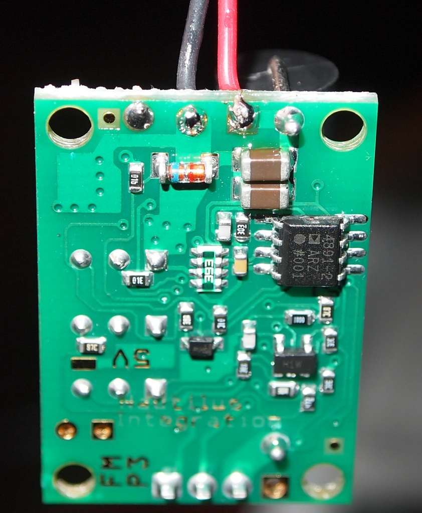
Put a wire in the hole from the underside and solder it in place.
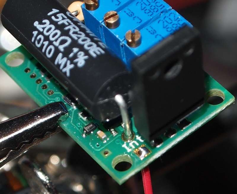
Now run this line over to the bottom of the driver to the V+ input on the driver.

Now strip the wire at the perfect length when pulled tight.
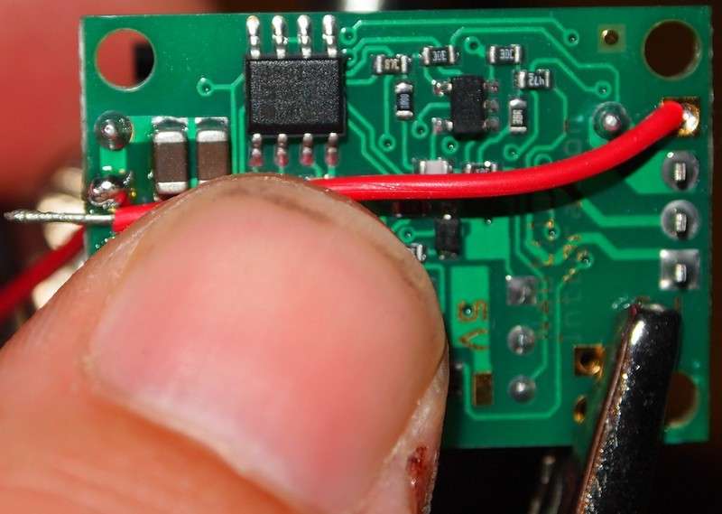
Clip the wire down to the right length.
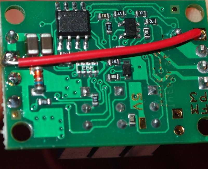
Solder the wire in place keeping it tight across the bottom.
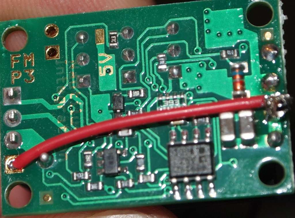
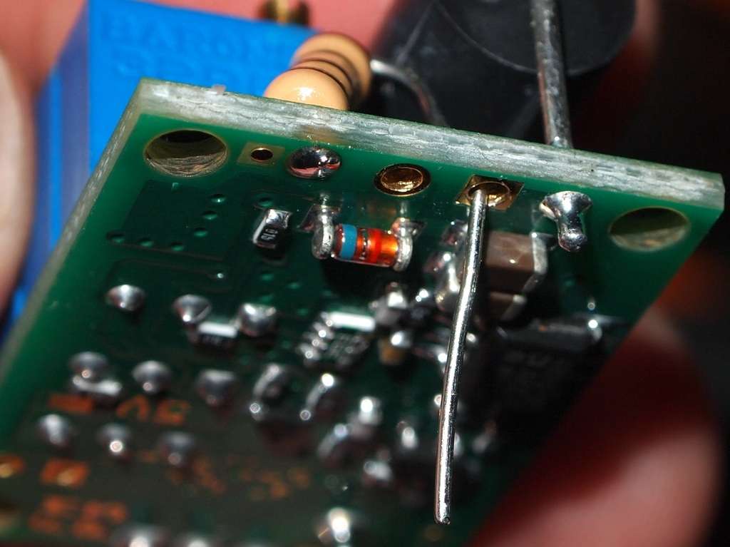
Now for the diode wires.
Here are the holes from the backside.

Solder you positive wire in place.
Solder your negative wire.

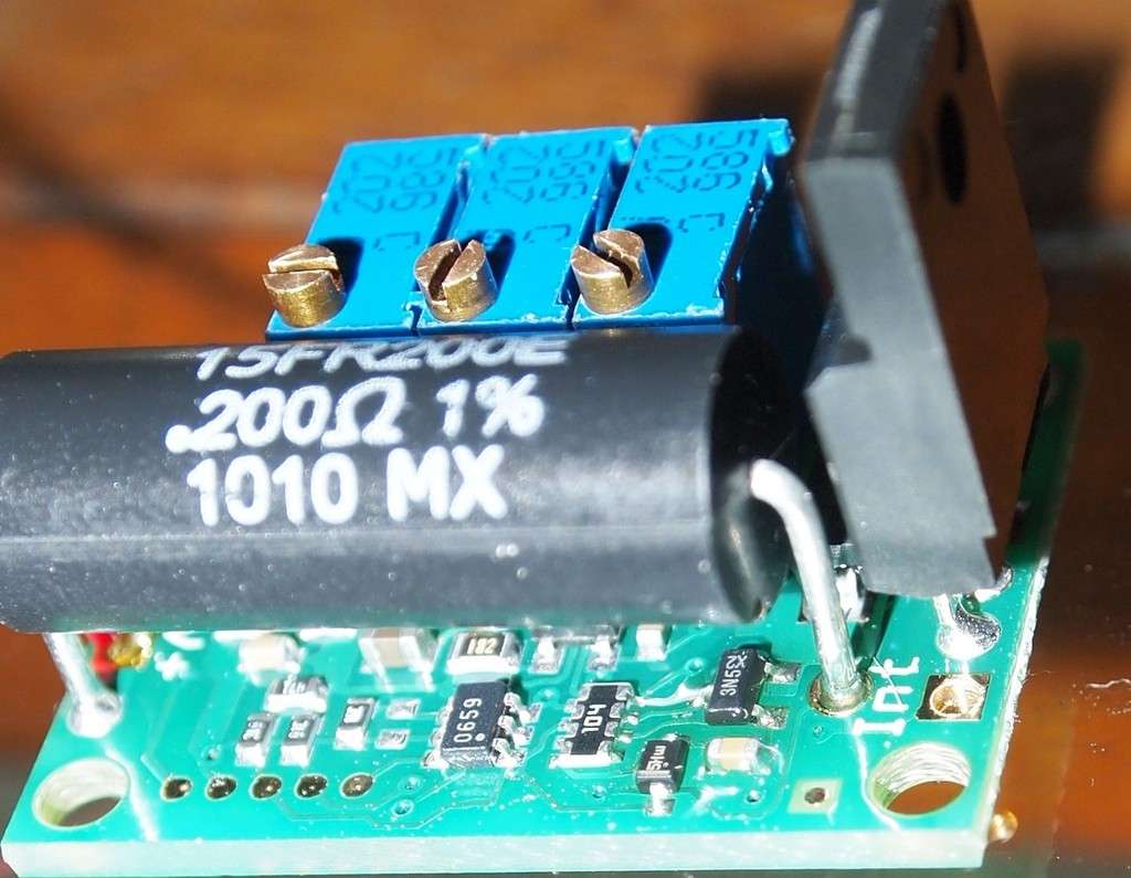
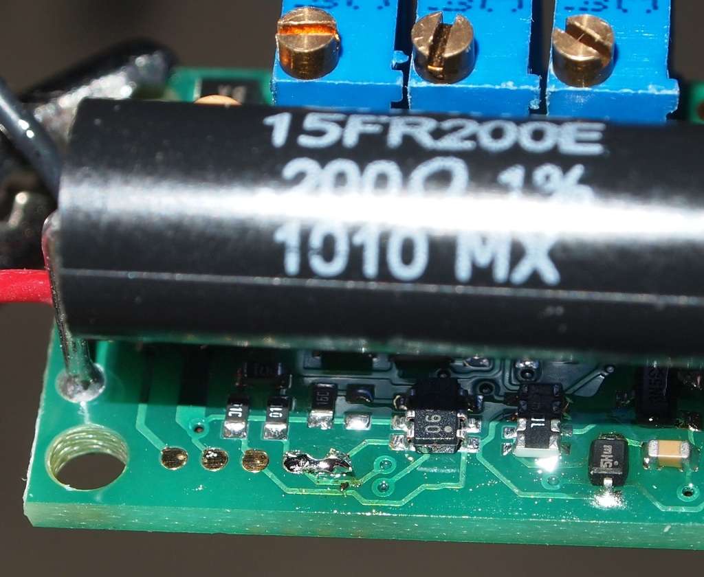
This unit comes with a default 7 second delayed startup. To say the least in a handheald that would be very annoying. If you look on the top side bottom left you will see five contact pads in a line.
Just dab some solder over the last two of them bridging the connection and the starup delay has been disabled.
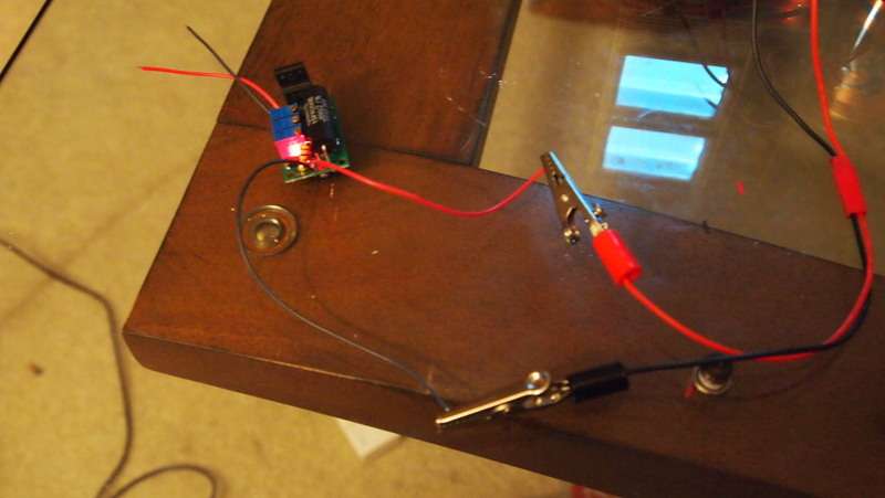
If you connect it to your power source with no diode you will see the light come on.
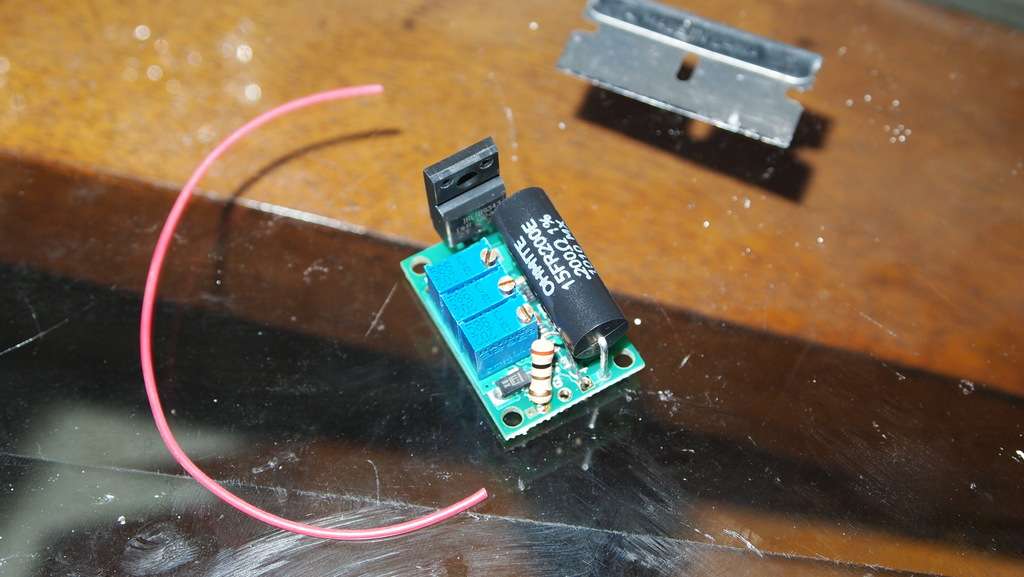
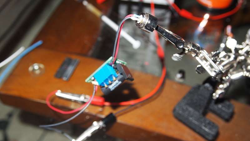
Now I soldered a diode onto the output wires on the driver.
I put the module in my Max Sink and was able to bolt the drivers heatsink onto the Max Sink's fins. Making a little labby.
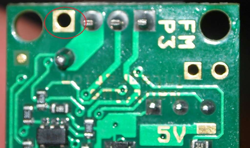
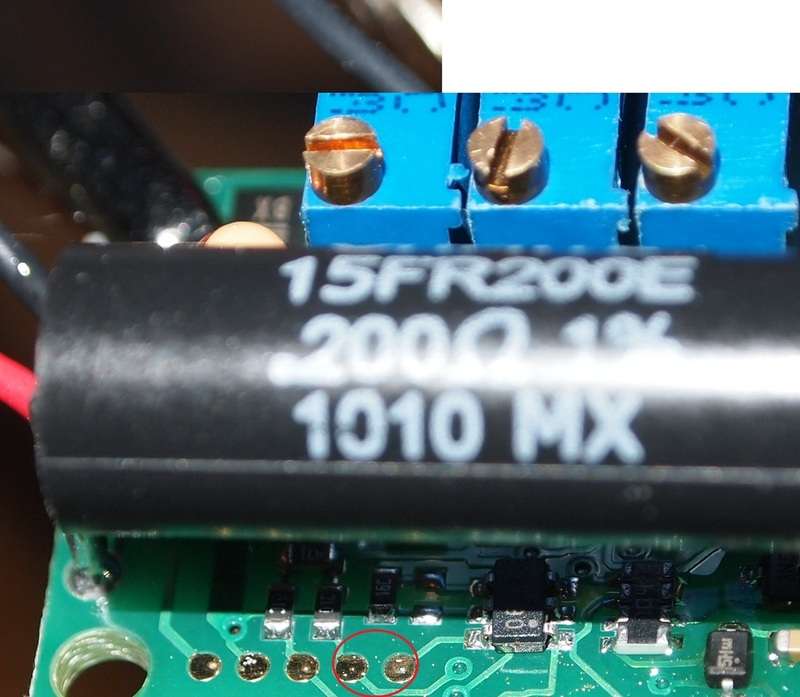
To adjust the power you need to turn the pot that is furthest from the heatsink. Circled in red.
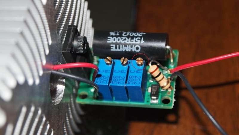
Now all you have to do is adjust the gain to the desired current and you are done.
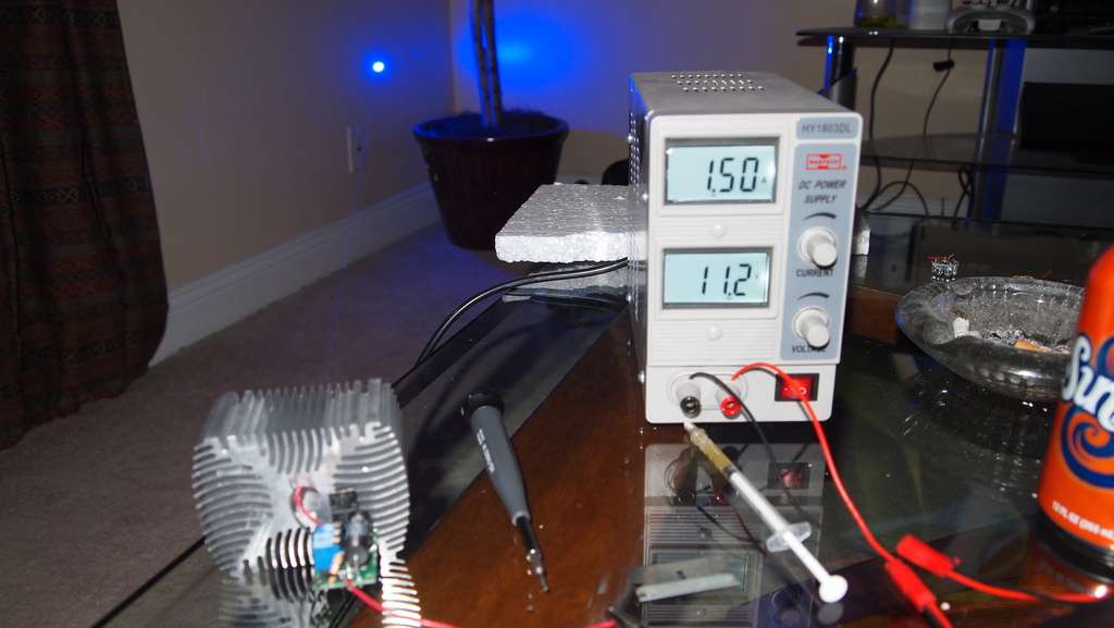
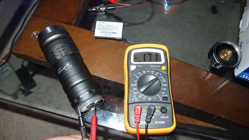
Also if you don't have a bench power supply you can use a battery and your DMM to set the current.
You can monitor current draw by using your DMM to complete the circuit like in the picture below. Set your DMM to 2M and put the positive line in the 10ADC slot.
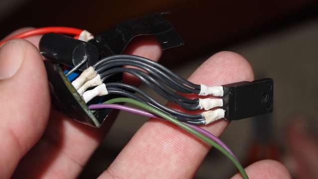
Depending on your hosts setup you can put the drivers heatsink on wires to extend it to reach your host heatsink. This is how it looked after moving it on my Frankenstein. I used three strands of pyro wire for each pin.
EDIT
I thought this video would help in deciding on your battery setup. The P3 can drive a 445 @ 1.6A with any voltage between 5.5V and 24V. So two 3.7V 26500's might be a good setup if we could find a host that fits the batteries and driver.
EDIT
That's it for now. I will update this thread when I get my next host with any other stuff that comes up in installing it. Hope you found this helpful.:beer:
Also if you would like to see more of my reviews and tutorials please visit my compilation page.
http://laserpointerforums.com/f51/d...difications-compilation-53944.html#post759223
Here is the specs and the module.
You neet to get a 1.5 K Ohm 1/2 Watt resistor which will be used to bridge the V+ and the M+. The M+ is the modulation input that can be used to adjust the current while in use. We will not be needing to adjust it in this manner so we will use the 1.5 K Ohm 1/2 Watt resistor to wire it in an always on full power mode.
Please disregard the actual resistor shown in the tutorial. I accidentally used a 1 Ohm resistor but the placement is the same.
Here is some info Jayrob got from drlava when developing his Mag kit.
I spoke to drlava direct on the phone to make sure I would be setting up the FlexModP3 properly...
He told me that if you have less than 11 volts supply, then you do not need a resistor at all. Just a wire to bridge across.
But if over 11 volts. You could use (he gave a specific Ohm but I forgot because we came to the following...)
I then told him that I wanted to use a resistor that would be fine for either set up to avoid confusion. (2 X Li-Ion vs 3 X Li-Ion)
That's when he told me that the 1.5 K Ohm 1/2 Watt resistor would be suitable for either set up. And I have been setting them up like that.
The driver works perfectly with either supply. I love the FlexModP3. It adjusts so smooth... 1/2 turn on the gain equals about 100mA's. It's an awesome driver if you have the room for it! Check this thread! (shameless plug)
I have a Word document in that thread linked, so you can print it out. It shows the basic set up of the FlexModP3. It's just a one page condensed version of what DTR shows in this thread...
Put the resistor in the holes and manipulate it into the position you want it to be.
Clip the resistor wire for the in the M+ hole. Then solder it in place.
Now get some wire out. I like to use the extremely flexible and burn resistant Flaminpryo wire.
Next shove the positive wire in the V+ hole along with the resistor already in place.
Clip the wires flush and solder them in place.
Add a negative wire in the G hole and solder it in place.
Your Input wires are done. And it should look like this.
The interlock is a safety feature that can allow the user to cut off the laser. It can be hooked up to an external switch in labbys but since I am using a handheld host I will wire it to be on all the time.
Here is where the hole is for the interlock on the back.
Put a wire in the hole from the underside and solder it in place.
Now run this line over to the bottom of the driver to the V+ input on the driver.
Now strip the wire at the perfect length when pulled tight.
Clip the wire down to the right length.
Solder the wire in place keeping it tight across the bottom.
Now for the diode wires.
Here are the holes from the backside.
Solder you positive wire in place.
Solder your negative wire.
This unit comes with a default 7 second delayed startup. To say the least in a handheald that would be very annoying. If you look on the top side bottom left you will see five contact pads in a line.
Just dab some solder over the last two of them bridging the connection and the starup delay has been disabled.
If you connect it to your power source with no diode you will see the light come on.
Now I soldered a diode onto the output wires on the driver.
I put the module in my Max Sink and was able to bolt the drivers heatsink onto the Max Sink's fins. Making a little labby.
To adjust the power you need to turn the pot that is furthest from the heatsink. Circled in red.
Now all you have to do is adjust the gain to the desired current and you are done.
Also if you don't have a bench power supply you can use a battery and your DMM to set the current.
You can monitor current draw by using your DMM to complete the circuit like in the picture below. Set your DMM to 2M and put the positive line in the 10ADC slot.
Depending on your hosts setup you can put the drivers heatsink on wires to extend it to reach your host heatsink. This is how it looked after moving it on my Frankenstein. I used three strands of pyro wire for each pin.
EDIT
I thought this video would help in deciding on your battery setup. The P3 can drive a 445 @ 1.6A with any voltage between 5.5V and 24V. So two 3.7V 26500's might be a good setup if we could find a host that fits the batteries and driver.
EDIT
That's it for now. I will update this thread when I get my next host with any other stuff that comes up in installing it. Hope you found this helpful.:beer:
Last edited:


")

") .
.