Welcome to Laser Pointer Forums - discuss green laser pointers, blue laser pointers, and all types of lasers

Buy Site Supporter Role (remove some ads) | LPF Donations

Links below open in new window

FrozenGate by Avery

How to set up the Flexmod P3 for a handheld laser

Im not trying to be a smart ass here but you keep calling it a heatsink, isn't it a MOSFET, a transistor? They produce heat and need to be attached to a heatsink but they are not heatsinks :).


Well four months ago I did not even know what a linear driver was. Electronics is not my strong suite but I have learned a lot in the short time I have been here. So I will never be offended at being enlightened. It is where the heat was generated so I called it a heatsink. But from now on MOSFET it is.;)


Quick question: the reason you attached a resistor from V+ to M+ is to have pretty much all the current flow into the V+ instead of M+ (as it is not needed) while maintaining 5V at M+ for modulation?


Actually I used a 3805 voltage regulator to drop it to 5V in the Frankenstein and drlava replied that I could do this.

One hint.. you don't need to regulate the 5V input on the driver, it is self limiting. You can just connect a 10k resistor from V+ to Mod+ to keep it on.

I just noticed in this he said to use a 10K resistor and I used a 1 Ohm resistor. I wonder if this will screw it up?:thinking:
 
Last edited:


I suspect that the purpose of the resistor is to limit the current to M+ while maintaining the potential difference of 5V :) Current flows in the direction of the least resistance, hehe. DrLava please correct me if i'm wrong in my assumption :)

P.S. Electronics is also not my field, I am Chemist/Biochemist :)
 
Last edited:
I need to learn more about this ^^^

What type of material should I start out with?

Not sure what you are asking here. Did you want to know the supplies needed to do this project?:thinking:
 
I need to learn more about this ^^^

What type of material should I start out with?

You should lurk around the forum and use its search features. Also Internet is your friend, so go ahead, load up your favorite search engine and type in a topic of interest :)
 
Last edited:
I just noticed in this he said to use a 10K resistor and I used a 1 Ohm resistor. I wonder if this will screw it up?:thinking:

Not seeing the schematic... the suggested 10K resistor would
probably be a Pull-Up resistor for the TTL input to not let the
input Float..
The only problem that I could see is that the 1 Ohm resistor
will draw more current though the TTL input circuit it is attached
to than the 10000 Ohm resistor.
(and that depends on the actual schematic)...


Jerry
 
What does TTL mean?

As a network engineer, TTL means time to live... :D

I understand everything he said now (except for TTL), just did some quick reading :)
 
DTR,

So I've been learning some stuff. Let me know if this is right.

Since you were outputing around 1800mW (before you cranked it up)

And you also set the current to 1.6A, you must have set the voltage somewhere around 1.125, correct?
 
What does TTL mean?

As a network engineer, TTL means time to live... :D

I understand everything he said now (except for TTL), just did some quick reading :)

TTL has to do with the type of modulation. A quick search in the box above with "TTL" will bring up many posts explaining it much better than I can.;)


DTR,

So I've been learning some stuff. Let me know if this is right.

Since you were outputing around 1800mW (before you cranked it up)

And you also set the current to 1.6A, you must have set the voltage somewhere around 1.125, correct?


I am supplying the driver 10-11V from 3 18650's in series and I am assuming the A140 diode is around 4.6-4.7V at 1.7A. If this is what you are asking.:beer:
 
a 338...its very "crude"

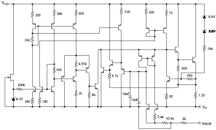
Why do you say that? Because it is one chip? Have you ever seen the schematic to an LM317? It's more complex than you think:

317.gif
 
Does anyone know what type of material I can read to start on this stuff... I would realy like to be able to read and understand this schematic, and others. I know I've asked about this before, but I got the typical "Search the forums." I'm looking for comprehensive material, from the beginning, for someone that has never done, or know anything about electrical engineering.

Thanks.

Why do you say that? Because it is one chip? Have you ever seen the schematic to an LM317? It's more complex than you think:

317.gif
 
Last edited:
I thought this video would help in deciding on your battery setup. The P3 can drive a 445 @ 1.6A with any voltage between 5.5V and 24V. So two 26500's might be a good setup if I could find a host that fits the batteries and driver.

 
@ liquid, you do not want to search the formus to learn how to read schematics. you can do a google search for "electronics schematics tutorial" or even youtube it. these will be helpful. and ttl is used for modulation or sometimes called blanking in laser scanners. ttl is 5v on and 0v off. but if you are using it in an RGB set up yo can only get so many colors. i actually learned this recently. so if you are interesed in color mixing you will want to use the anolog feature of the flex mod and then you can color mix all you want.

michael


Back
Top