Welcome to Laser Pointer Forums - discuss green laser pointers, blue laser pointers, and all types of lasers

LPF Donation via Stripe | LPF Donation - Other Methods

Links below open in new window

ArcticMyst Security by Avery

Testing laser diode?

IsaacT

0
Joined
Aug 25, 2010
Messages
5,947
Points
83
Is there a way to test a diode to make sure that:
1. The diode still works
2. The approximate wavelength of the diode

I need to know because I don't have any drivers since it is my first diode. I don't want to purchase a diode until I know that it isn't IR and more importantly, it hasn't been damaged by the extracting process. Thanks!

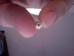
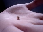
Below are thumbnails of the diode I am talking about, don't know if a picture will help but better safe than sorry.
 

Attachments

  • Photo on 2010-09-09 at 12.57 #2.jpg
    Photo on 2010-09-09 at 12.57 #2.jpg
    50.6 KB · Views: 1,027
  • Photo on 2010-09-09 at 12.57.jpg
    Photo on 2010-09-09 at 12.57.jpg
    58.6 KB · Views: 1,207


Morgan

0
Joined
Feb 5, 2009
Messages
2,174
Points
0
You can first do a continuity test between each of the pins and the case to identify which one is the case pin. I don't know if there are any specific procedures to follow this because whenever I've tried to use the diode test funtion on my DMM, I had no luck. Try using this funtion if you have it. between the case pin and each of the other two pins. If you identify the polarity then you know how to hook it up at least.

IIRC, the red should have a blueish tint to the AR coating and IR should have a greenish tint. I read this recently but can't for the life of me remember where and after a good search, can't find it. It makes sense though as AR coatings for red are blue and IR filters show green.

IR diodes will likely be case positive and reds case negative. If you've determined the case pins and polarity then try the diodes as if they are IRs. This way, at low voltage and current, you will either see IR light, (using your camera phoen to view), or nothing and at the low current, you will likely not do any damage to the red diode hooking it up in reverse polarity. This is, at least, how I identified my first diodes and nothing bad happened. Wait for a contradiction against this advice though as it is a little speculative and it's been a while since I extracted an unknown diode.

G'luck,

M
:)
 

IsaacT

0
Joined
Aug 25, 2010
Messages
5,947
Points
83
How do I know which one is the case pin? is it the one that is not linear with the other two? like you have the two outside pins that if you connected with a line would go through the center of the diode and then the one that is higher up from those two aligned more on the vertical axis. Would it be that one that is higher?
 

Morgan

0
Joined
Feb 5, 2009
Messages
2,174
Points
0
No, you touch one probe of your DMM to the metal case or gold base plate and touch each of the pins in turn with the other probe. The DMM should have a continuity test setting that gives a beep when there is little or no resistance in the path. Alternatively you can measure using the Ohms setting. The lowest reading will be the case pin. I am assuming this is not a BR drive of any type as BR diodes tend to have no case pin connected!

It's hard to see scale in your photos but these certainly look to be a TO18 package. They should be 5.6mm in diameter at the widest point and these are the common size we usally use. The Aixiz modules take this size.

M
:)
 

IsaacT

0
Joined
Aug 25, 2010
Messages
5,947
Points
83
Good eye! ya, 5.6mm around the gold....are the numbers that are printed on the side good for looking anything up? Just out of curiosity, because they seem to be on all 3 diodes I have come into contact with.
 
Joined
Aug 15, 2009
Messages
1,443
Points
48
Testing for continuity can put a reverse voltage across the diode, any reverse voltage across the diode will almost certainly damage or kill the diode. In my experience nearly all diodes are case positive, although those were all IR I think.
 
Joined
Jun 12, 2010
Messages
892
Points
0
There's another way- you can use an LED tester. They're available for cheap, and are essentially a constant-current driver.

Often they will have a low-current range (20-50mA) which is enough to get a diode to threshold.

Simply plug the diode into the correct set of holes for the correct current, and it will lase.

At those low currents, a mistake won't kill the diode.
 
Joined
Aug 15, 2009
Messages
1,443
Points
48
Incorrect. Low power diodes easily blow at 50mA.
Also, the reverse current laser diodes can withstand is usually a few microampere, so putting it in reversed kills it.

You can assume a pinout and apply a current, but that's taking chances. I think on the famous laserfaq is a lot of info. I think a nice procedure is to apply a voltage with a lab power supply and very slowly and carefully increase is up to about 2v. Is by then there's no light, then you've probably put it in backwards, but the voltage isn't that high that it blows. Off course when you get light out you should turn if off immediately, a voltage regulation is quite instable.
Of course the light can be IR, so wear IR goggles covering from around 750nm to above 1000nm, preferably above 1400nm and use an IR card to see if the diodes are IR diodes.

But you really should check Sam's laserfaq.
 
Joined
May 4, 2009
Messages
5,443
Points
113
The case pin will look like it's comming right out of the metel case the other two pins go through insulators, there is no mistaking this !
IR diodes are case positive, with that rarely being wrong !
Using a ohm meter is not a good idea as if it uses a 9 volt battery for the ohms check you could reverse polarity the LD and kill it !
Best to follow standard diode pin out's to determin the diodes polarity.
If you can not find the correct pin-out for your diode the best way to find out is use a low voltage set your lab supply to 1.8-2.2 volts and apply it quickly if you don't see some light reverse the polarity and try again this is for red's and IR diodes, for BLU type diodes increase the voltage to 3.2-3.7 volts ;)
Pyro...


How do I know which one is the case pin? is it the one that is not linear with the other two? like you have the two outside pins that if you connected with a line would go through the center of the diode and then the one that is higher up from those two aligned more on the vertical axis. Would it be that one that is higher?
 
Last edited:

IsaacT

0
Joined
Aug 25, 2010
Messages
5,947
Points
83
Thanks for that great explanation Flaminpyro! Actually got a red light out of one!


Top