Welcome to Laser Pointer Forums - discuss green laser pointers, blue laser pointers, and all types of lasers

LPF Donation via Stripe | LPF Donation - Other Methods

Links below open in new window

ArcticMyst Security by Avery

TECs used as LPM sensors failures...

Joined
Sep 20, 2008
Messages
17,622
Points
113
We've been working on a new High Power Thermopile
Sensor coating capable of read to 12 watts for a new
LaserBee LPM product...

Today we started the final tests and as we ramped up
the adjustable 40 Watt Laser to near 12 watts the LPM
reading started to slowly drop and at 8 watts dropped
right down to zero... I was sure it was the Laser.

Tuning down the Laser and checking the output with
our Newport LPM the Laser was just fine.

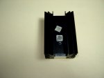
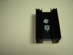
Under close examination of the new TEC that was sealed
with silicone on the edges it seems the solder used to
hold the top plate to the bottom plate by the PN junctions
came unsoldered....:eek:

In 10 years of working with these TECs I've only seen this
happen one time before 11 years ago when we tried to bake
a coating onto a TEC at 350 Deg F for 20 minutes. The TEC
obviously fell apart into many pieces.

This now has me wondering about small TECs subjected to
High Laser power for extended periods. If only part of the
PN juctions are damaged and it is not a catastrophic failure
like mine.... is the TEC still calibrated to the LPM...:undecided:

Pics are attached below...


Jerry
 

Attachments

  • Tec Damage1.JPG
    Tec Damage1.JPG
    150.1 KB · Views: 70
  • TEC Damage2.JPG
    TEC Damage2.JPG
    149.4 KB · Views: 67


Joined
Sep 20, 2013
Messages
17,423
Points
113
Wow. That TEC in the Thumbnails came completely apart. Seems like you would want a larger TEC so the surface area could absorb more of the heat. That, or a different one that can take temperatures that high.
 
Joined
Sep 20, 2008
Messages
17,622
Points
113
I E-Mailed the supplier to know the melting
point of the TEC in question. I think it is a
low temp solder that was used. Hopefully I
get a response by tomorrow.

Jerry
 

diachi

0
Joined
Feb 22, 2008
Messages
9,700
Points
113
I E-Mailed the supplier to know the melting
point of the TEC in question. I think it is a
low temp solder that was used. Hopefully I
get a response by tomorrow.

Jerry


Should be some available that use higher temperature solders, might be a suitable replacement. Keep us posted? :D
 
Joined
Dec 15, 2014
Messages
6,782
Points
113
Jerry,
Glad to see your testing your skills to put out another high power capable LPM. Im sure you will pull it off. I purchased the last 7+ W laserbee LPM when they were still available. Still my best one out of all of them with data logging. Keep up the great work hope it works out .

Rich:)
 
Joined
Sep 20, 2013
Messages
17,423
Points
113
350 degrees F is just short of 177 degrees C. That is pretty low temperature solder.
 
Joined
Jul 27, 2007
Messages
3,642
Points
63
As someone who has looked into this issue before, higher temperature TECs are not very common and if you can find them the prices are not good. Usually the ones designed for power generation use higher temperature solder.

The problem comes from the fairly high thermal resistance of an unpowered TEC. The hot side reaches the solder melting point even though the other side is completely cool.

While experimenting with high temperature TEC coatings I was looking at a laser activated ceramic. Putting it into a laser engraver resulted in a KRSHH sound as all the tiny TEC junction cubes scattered in the bottom of the machine.
 
Joined
Sep 20, 2013
Messages
17,423
Points
113
Hi, MarioMaster. Been awhile since the last time I saw you post. Good to see you again. + rep. :yh:
 

Radim

0
Joined
Aug 17, 2016
Messages
1,458
Points
83
Oh, Jerry, that looks terrible. Hopefully you will solve this soon. Maybe larger TEC, maybe larger heatsink as well to disipate heat better? Combination of both?
 
Joined
Sep 20, 2008
Messages
17,622
Points
113
350 degrees F is just short of 177 degrees C. That is pretty low temperature solder.

The 350 degree test was 10 years ago...:beer:
I don't know how hot the small TEC got to
with the High Powered Laser on it before it
destructed.

Oh, Jerry, that looks terrible. Hopefully you will solve this soon. Maybe larger TEC, maybe larger heatsink as well to disipate heat better? Combination of both?

Been trying to contact the Seller for info...
So far no luck... I think it may be due to the
CHinese New Year crap. A pain in the butt
for the non-Chinese working stiff... :cryyy:

Yeah... a larger surface TEC may be the solution
but it increases the 100% Response time.


Jerry
 

Radim

0
Joined
Aug 17, 2016
Messages
1,458
Points
83
Yes, Jerry, that will take some time. In this case, larger heatsink, maybe a little fan (but that might be too complicated). Who knows, what quality (and type) of solder they use.
 
Joined
Sep 20, 2008
Messages
17,622
Points
113
Yes, Jerry, that will take some time. In this case, larger heatsink, maybe a little fan (but that might be too complicated). Who knows, what quality (and type) of solder they use.
The Heatsink is large enough... IMO

If you look at the pic in the 1st Post you
will see that the PN juctions are still soldered
to the rear ceramic plate attached to the
heatsink.

It was the heat produced by the Laser that
melted the solder holing the front ceramic
plate to the PN junctions.

The heatsink wasn't even warm when the
TEC failed. The Laser was on the TEC for
maybe 10-15 seconds. Not enough time to
heat up the mass of the heatsink.


Jerry
 

Radim

0
Joined
Aug 17, 2016
Messages
1,458
Points
83
In that case it seems to be really something wrong with sensor itself. Maybe defective unit? Let's see, they should replace it or redesign if there is problem of design. I assume the contact between heatsink and the sensor was well made - since that might also cause that problem of bad heat transfer to the heatsink.
 
Joined
Mar 27, 2011
Messages
506
Points
63
Hi jerry, i thought i need to give you my experiences:

  1. When my several first trial of using carbon coated and hitting my Hyperion LPM sensor (6x6mm) with 6W laser, the solder that hold the PN junction is indeed melting, that's why i wrote in the user manual and information thread with "avoid knocking the sensor while it's hot" because the PN junction can broke/fall apart.
  2. It is also occured that the excessive heat on some of the PN junction could cause a premature death of that particular PN junction, i could confirm this as "PN junction (silicone) death" because the PN is still aligned perfectly without visible physical deterioration. There is one case where the buyer of Hyperion having his sensor died after measuring about 6W.
  3. The PN junction usually hold in place by usual solder which melts at 230°C or SnAu which melts at 280°C, yet i measure the surface of the TEC when hit by 6W laser could reach 700°C


Here is what i wrote in my information thread, might helps everyone who missed it:
  • The default sensor is a 6x6mm peltier. It can be bought here. As you can see those sensor are rated for 200°C.
  • A normal operation (e.g when reading 3600 mW laser) can cause the sensor to heat up to >300°C which is above the Tmax of those peltier and can melt the solder joint of the PN junction. That's why you need to avoid knocking the sensor while it's hot.
  • Under normal commercial warranty, operating above maximum rating will void the warranty. That's why even our "normal" operation will void the warranty from the peltier's manufacturer.
  • While focusing the laser to the surface of Hyperion sensor doesn't degrade the coating, it will stress out the particular PN junction behind the ceramic where your laser is being pinpointed. This might cause a temporary or permanent failure to the sensor.
  • It is better if you point your laser at different surface area of the sensor on each measurement to prevent stressing the PN junction.
  • Measuring high power laser continuously can cause thermal runaway on the sensor due to the nature of semiconductor (it'll die and cant measure anything anymore). Most semiconductor device/IC has thermal shutdown feature that will shutdown the device/IC when it's reach 150°C, yet our normal operating temperature reach two fold of that and it doesn't have that feature. In conclusion, the recommended max is 30 secs when measuring above 5W laser (15W for uncoated sensor), and it's better if you used forced air to cool the heatsink of the sensor, set the fan to blow facing the back of the sensor.
  • Furthermore, the sensors itself (the coated sensor) are not strong enough to be heated by laser with power more than 7W (23W) (even though the coating is strong enough for it). All commercial thermal sensors capable of measuring high power lasers are using metal to detect the heat which is not a problem for it, on the other hand, this sensor is a tiny semiconductor that is breakable by heat.


My conclusion: That is not a defect nor bad sensor, it is completely normal as it is the limitation of the TEC itself. ;)
 

CurtisOliver

0
LPF Site Supporter
Joined
Jun 12, 2015
Messages
7,610
Points
113
Unfortunately due to the lasers very localised heat a larger TEC would not help very much. The laser rapidly heats up the TEC in a specific area. Only a larger input beam (lower beam intensity) or higher temp solder will be beneficial.
You could always invest in graphene as a super fast heat dissipator. :p

What heatsink are you using Jerry? The idea is to draw the heat away from the centre as quickly as possible. So a special radial heatsink would be best as it would transfer heat quickly from the centre out towards the edges.
 
Last edited:
Joined
Sep 20, 2008
Messages
17,622
Points
113
@ Curtis...
We use the same Heatsink as on the LaserBee AX3 on
our website with a custom machined solid aluminium
block on the rear held on by Thermal Epoxy. Our Head
weighs more than an OPHIR head.

By using a larger 15 X 15 TEC and a larger Laser beam
diameter the Power Density would be lower hence a
lower PN junction temperature...IMO
That would probably be tested today if nothing else
goes wrong...;)

@ Astralist..
Yes I agree with your testing results and precautions.
Remember that TECS are manufactured with different
melting point solders. Our small TECS may have been
assembled using very low Temp solder.

You may be experiencing higher TEC temperatures due
to the small 45 gram heatsink.

BTW your TEC link seems to be dead...:beer:


Jerry
 
Last edited:


Top