

Pman
0
- Joined
- Nov 28, 2012
- Messages
- 4,441
- Points
- 113
Finished this a couple days ago and it was a bit of a pain in the butt but also satisfying as it took quite a bit of time to get it right mainly because I kept changing my mind on how I wanted to get the wiring and components arranged.
Although I have lasers in many shapes and sizes pens tend to get be my favorite and I still have some Laser66 pens in gold, silver and black standing by awaiting funds to complete. As far as I understand he has a lot more of these pens and its best to buy directly from him and not go through his email. If someone can offer up the link that would be great.
Feel the need to mention that the gold plated ones will lost their plating and start to look more and more silver like the silver ones as the laser is handled. It's a very thin layer of gold but I will also note that the gold ones can be turned into the nice shiny silver with the use of NEVR-DULL so don't despair")
As usual I tend to show lots of pics so others can copy if they want so I'm sorry if you have a really slow service but this is what I do.
***Before I start if anyone can help out with additions or identifications of diode case +, - or n (neutral) in the following thread it would be greatly appreciated as it benefits all of us. Post #9 specifically:
http://laserpointerforums.com/f67/diode-driver-combination-wiring-96176.html#post1399847
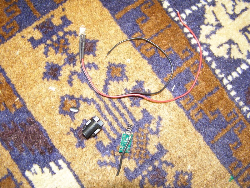
So here are some of the basic parts I need to achieve the goal. I believe the LED is a 12V rated one and I received 3 of them from Crazyspaz awhile back but don't know where he acquired them from. There's also an un-populated board, tiny clear plastic pin on the left, plastic board holder and little oval plastic piece that has a little piece of sticky tape on the other side to attach to the button hole on the host. The wire wasn't originally there on that board but soldered on before I took the pic:
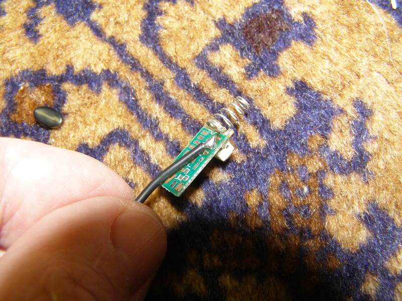
Here's another pic of the wire I added to the back of the board. You will see why it's there and soldered to one of the negative spots (going to be host negative) in a moment:
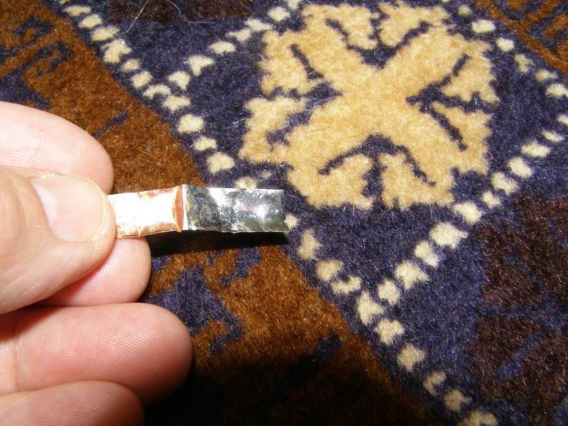
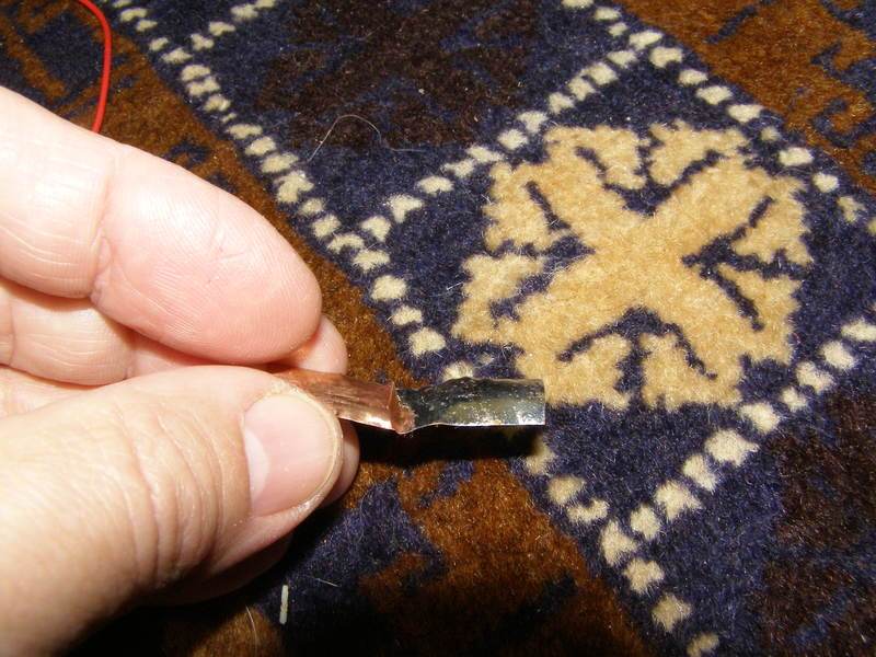
I took a piece of thin copper and tinned it all with solder both sides just to make it slightly thicker and make it conduct better than copper that could tarnish:
So here's a pic of the LED along side the board in its holder before I added that piece of copper. The piece of copper will end up sitting on the opposite side of the holder shown here so that when the whole thing is pushed inside the host it will be snug against the host wall. The LED is actually too large to fit into the host properly and will be dealt with:
Not a good pic but I quickly realized that I wouldn't be able to fit the LED in this way especially because on the anode side theirs a resistor under the heat-shrink that sticks way out and will get in the way of putting everything together:
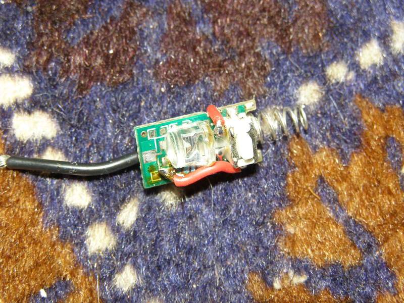
So, this is what I ended up doing to make everything fit and still get a great result. Remove the heat-shrink from the LED, remove the resistor and cut the pins really short. Took my dremel and flattened one side of the LED and then cut the length down. Epoxied it down onto the board right up against the button with the cathode side oriented the way I wanted to connect it to the negative of the board. It's also moved closer to the one side so I could fit the resistor up against it (glued) on the other side and wired correctly. You can also see a little notch I made on the side to fit the wire through:
Should have grabbed a piece of black wire even though it doesn't matter:
This shows the added resistor soldered to the anode side of the LED and then the other end soldered to the switched side of the button:

Before I go any further here's the diode I had already pressed in and attached the B-Linear driver to:
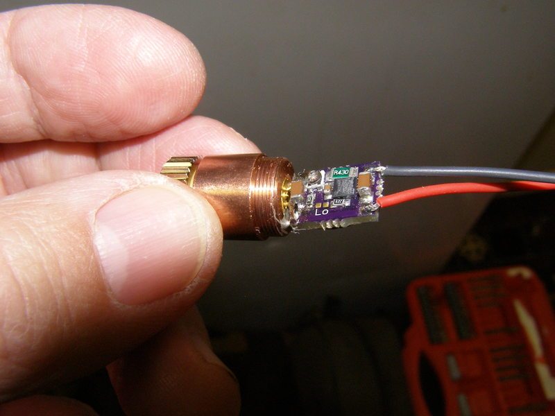
Driver is set to max and I attached a nice copper piece to the backside for cooling although it's basically a moot point considering the laser can't be on long due to the lack of any added heat-sink with the host. There's a bit of Arctic Alumina there to make sure the driver isn't going to move if the power input wires end up twisting although it's not really necessary here but more of a habit:
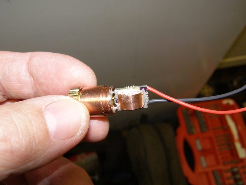
So now I have to make it all come together and sit inside the host to just the right length to align the button properly while press fitting it straight in. I soldered the driver wires to the switch on the back side to the appropriate spots on the board which were different from any of the already soldered spots I had used and would not interfere with the plastic board assembly sliding in place over it all:
You can see how it came together with the holder:
Keeping things in place:

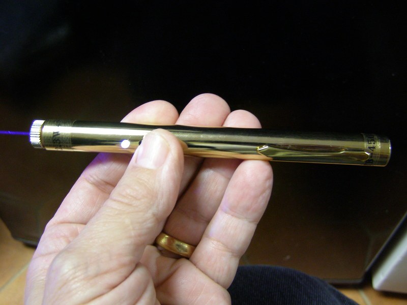
Finished product with fingerprints all over it. Uses (2) Efest 10440 host negative (very small neo magnet on the - battery end for good connection to host back cap). You can see the small clear plastic piece that fits into the really small hole made for it in front of the button hole. Obviously I add the button too:
Pic in lit room you can still see the beam and lit indicator LED:
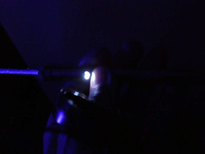
A bit of a shaky pic. 2W+. I am very conservative on duty cycle and it gets warm very quick at that kind of output so personally I wouldn't run it past 10 or so seconds from a cold start. I did a quick comparison to a 2.2W M140 and visually I couldn't see any difference in brightness.
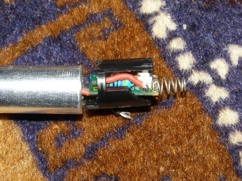
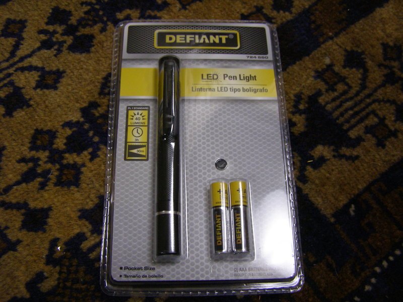
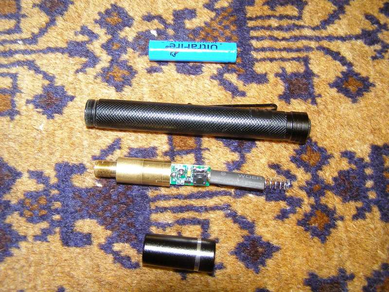
As a bonus I was at Home Depot a week ago and picked up a little (2) AAA flashlight for about $6 and found that it is absolutely perfect for adding a 5V Fasttech module with no modifications other than a long spring, jumpering the switch and a 10440 battery:

Although I have lasers in many shapes and sizes pens tend to get be my favorite and I still have some Laser66 pens in gold, silver and black standing by awaiting funds to complete. As far as I understand he has a lot more of these pens and its best to buy directly from him and not go through his email. If someone can offer up the link that would be great.
Feel the need to mention that the gold plated ones will lost their plating and start to look more and more silver like the silver ones as the laser is handled. It's a very thin layer of gold but I will also note that the gold ones can be turned into the nice shiny silver with the use of NEVR-DULL so don't despair
As usual I tend to show lots of pics so others can copy if they want so I'm sorry if you have a really slow service but this is what I do.
***Before I start if anyone can help out with additions or identifications of diode case +, - or n (neutral) in the following thread it would be greatly appreciated as it benefits all of us. Post #9 specifically:
http://laserpointerforums.com/f67/diode-driver-combination-wiring-96176.html#post1399847
So here are some of the basic parts I need to achieve the goal. I believe the LED is a 12V rated one and I received 3 of them from Crazyspaz awhile back but don't know where he acquired them from. There's also an un-populated board, tiny clear plastic pin on the left, plastic board holder and little oval plastic piece that has a little piece of sticky tape on the other side to attach to the button hole on the host. The wire wasn't originally there on that board but soldered on before I took the pic:
Here's another pic of the wire I added to the back of the board. You will see why it's there and soldered to one of the negative spots (going to be host negative) in a moment:
I took a piece of thin copper and tinned it all with solder both sides just to make it slightly thicker and make it conduct better than copper that could tarnish:
So here's a pic of the LED along side the board in its holder before I added that piece of copper. The piece of copper will end up sitting on the opposite side of the holder shown here so that when the whole thing is pushed inside the host it will be snug against the host wall. The LED is actually too large to fit into the host properly and will be dealt with:
Not a good pic but I quickly realized that I wouldn't be able to fit the LED in this way especially because on the anode side theirs a resistor under the heat-shrink that sticks way out and will get in the way of putting everything together:
So, this is what I ended up doing to make everything fit and still get a great result. Remove the heat-shrink from the LED, remove the resistor and cut the pins really short. Took my dremel and flattened one side of the LED and then cut the length down. Epoxied it down onto the board right up against the button with the cathode side oriented the way I wanted to connect it to the negative of the board. It's also moved closer to the one side so I could fit the resistor up against it (glued) on the other side and wired correctly. You can also see a little notch I made on the side to fit the wire through:
Should have grabbed a piece of black wire even though it doesn't matter:
This shows the added resistor soldered to the anode side of the LED and then the other end soldered to the switched side of the button:
Before I go any further here's the diode I had already pressed in and attached the B-Linear driver to:
Driver is set to max and I attached a nice copper piece to the backside for cooling although it's basically a moot point considering the laser can't be on long due to the lack of any added heat-sink with the host. There's a bit of Arctic Alumina there to make sure the driver isn't going to move if the power input wires end up twisting although it's not really necessary here but more of a habit:
So now I have to make it all come together and sit inside the host to just the right length to align the button properly while press fitting it straight in. I soldered the driver wires to the switch on the back side to the appropriate spots on the board which were different from any of the already soldered spots I had used and would not interfere with the plastic board assembly sliding in place over it all:
You can see how it came together with the holder:
Keeping things in place:
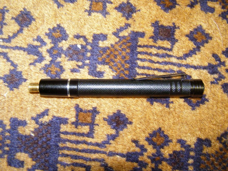
Finished product with fingerprints all over it. Uses (2) Efest 10440 host negative (very small neo magnet on the - battery end for good connection to host back cap). You can see the small clear plastic piece that fits into the really small hole made for it in front of the button hole. Obviously I add the button too:
Pic in lit room you can still see the beam and lit indicator LED:
A bit of a shaky pic. 2W+. I am very conservative on duty cycle and it gets warm very quick at that kind of output so personally I wouldn't run it past 10 or so seconds from a cold start. I did a quick comparison to a 2.2W M140 and visually I couldn't see any difference in brightness.
As a bonus I was at Home Depot a week ago and picked up a little (2) AAA flashlight for about $6 and found that it is absolutely perfect for adding a 5V Fasttech module with no modifications other than a long spring, jumpering the switch and a 10440 battery:


")
 Would have bought a couple packs of them to mess with. They don't sell them online. I just found it really odd that the one I bought has the perfect space between the halves to hold the module right with no wiggle and fully conductive.