Welcome to Laser Pointer Forums - discuss green laser pointers, blue laser pointers, and all types of lasers

LPF Donation via Stripe | LPF Donation - Other Methods

Links below open in new window

ArcticMyst Security by Avery

8X Diode Murder fund

IgorT

0
Joined
Oct 24, 2007
Messages
4,177
Points
0
Ok, so with the first two LG 8x diodes i went in 10mA steps up to 360mA..

Later we decided not to be so evil to all of them, so i am testing them with just a few steps measuring Po and Vf for: Ith, 40mA, 80mA, 120mA, 160mA and 200mA..

This is what eventually became my standard testing protocol for 6x's...
It is only a few steps (i'd go crazy if i had to plot EACH of the GGWs in 10mA steps - i know, because i did it at the start) but from experience i know two things:
1. If a diode is good, it will make a "straight" line regardless of the resolution i test it in. In fact, when i plot it in 5 40mA steps, the line will be more accurate, since less heat will be able to develope during the shorter time.
2. If a diode is bad, the 5 step plot will show bends in it, the 40mA steps will bring widelly varying power increases, allowing me to eliminate the weird diode for more detailed testing...


Another thing i know is, that among ALL the GGWs i tested so far (over 70 by now), only one ever displayed "kinks"..
Many others were extremelly low efficiency, so much lower from the rest, that they actually formed their own group, separated from all the normal GGWs, including the low efficiency ones.

As a result there is a gap in the 61 GGW Plot, where there is not one diode that would peak between 160 and 170mW at 200mA - low efficiencies start at over 170mW and the BAD diodes all fall short of 160mW... And the one with kinks was the lowest of them all by far!

Based on that, i believe it is safe to assume, that these diodes came from prototype sleds, and were themselves prototypes, or intentionally purchased reject diodes, used simply for sled optics adjustments and testing...


Diodes from drives never display such bad characteristics, because they go through many tests, before they are released on the market.


So this short five (well, six counting Ith) step test allows me to make accurate 8x plots, where i can extrapolate the higher numbers from, without having to actually push the diodes to 360mA and potentially endanger them, before we even know what a safe power is!

It separates them by efficiency, and allows me to pick out the weakest two.


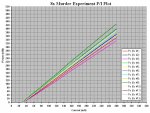
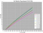
Additionally, as i explained in the Red vs. Blu Comparison thread, i want to compare these 8x's according to their ACTUAL efficiency, meaning i am plotting them against their calculated electrical input power, not just input current. Luckily for me, Excel is multiplying the numbers by itself... :angel:

Also, i have a column automatically calculating their efficiency, and i can already see that it peaks between 160 and 200mA, so in the end, the most accurate way of picking the two weakest ones is just this efficiency column, or rather the separate efficiency plots...


So all i need to do now is type in a lot of numbers and select the two "winners"... :evil:
(After i fetch myself a big mug of coffe...)


P.S. If anyone tries to do a Po/Pe comparison plot of multiple diodes in Excel, you HAVE to use the "X/Y Scatter" type of chart... If you use a regular line-chart, it will NOT draw the plots related to the diode's el. input power, but related to the number of the row/column the data is in!

I realized this during the Red vs. Blu Comparison, where i couldn't convince Excel to make meaningful plots. Rkcstr figured out what i was doing wrong - Thanks Rkcstr!

Luckily the error there was huge and couldn't be overlooked, while it could easily be missed when comparing diodes of the same type, which is why i am mentioning it.

You need to be able to input both X and Y data for each plot separatelly, and this only works with the "Scatter" chart....


Krutz

0
Joined
Nov 21, 2007
Messages
1,733
Points
48
aaahhh! someone get this man his coffee! cant stand to wait any longer! so close! :)
all eyes on you, igor!

manuel
 

IgorT

0
Joined
Oct 24, 2007
Messages
4,177
Points
0
Well I've decided I'm going to use a 6X in my scanner build, due to the various costs, risks of modulation screwing it up and what not. But I'm still interested in an 8X going through some tests, so what I might do is start a thread in the scanner section and see how people are willing to donate for a 8X diode for testing.

In fact, it might be a good idea to test a 6X as well under scanner conditions... maybe I'll set up a 'diode under scanner conditions' fund, lol. (EDIT: And then he did http://laserpointerforums.com/f47/diodes-under-scanning-conditions-test-fund-45018.html)

I have a bunch of GGWs, already sorted by efficiency...

I could start with the very low efficiency ones at 160mA just to see what happens, after they die, move on to a low efficiency one (which already falls under normal working diodes)... The very low i'd kill for free to get some basic idea of what to expect, the low for cheap (two for one) - as long as you supply the driver and whatever modulates it.... In the end that would make three dead diodes for the cost of what i paid for each.

If you want to test a high efficiency one, you'd have to supply it, cos i'm slowly running out of them.


Otherwise, SightFx might also be interested in just this, he wanted to supply a GGW and one of his kits, to test together..

But i think he was mostly worried about operating temperature and not power...


Sorry, I meant FlexMod :)

That makes more sense, yes... I simply couldn't understand how one would modulate a FlexDrive..

I was starting to think it has a secret modulation pin hidden somewhere.. :thinking:
 

HIMNL9

0
Joined
May 26, 2009
Messages
5,318
Points
0
I was starting to think it has a secret modulation pin hidden somewhere.. :thinking:

Well, actually, it have a "secret hidden" modulation pin ..... sorta of, at least :p

Vsel pin permit you to switch from output levels ..... it's just too difficult to take the pin from under the IC and use it ..... :crackup:

:D
 

IgorT

0
Joined
Oct 24, 2007
Messages
4,177
Points
0
The magic has begun . . . . . .

Peace,
dave

Indeed... :yh:


Otherwise, i was trying to decide, if i should make the cycler tests in a laser body (like i initially sugested), or on my huge pre-testing heatsink.

I just did a short simulated cycler run, and i am thinking i should not be using a laser as the host for the test.

Initially i said i will cycle a laser, to keep the test as realistic as possible.

But just now i checked what happens with the temperature of the laser, using an open can at 520mA (1.422W of heat). This is more heat than the first 8x will produce while it's running, but that's why i noticed the results sooner.

The laser started at 20°C before the test. After the first minute, it was at almost 22°C. During the OFF part of the cycle, it seemed to have cooled down back to 20°C, but during the second ON cycle it warmed up to 22°C much faster.

Basically, the temperature only dropped to ambient on the outside, while the core still kept some heat. So every cycle started heating up from a higher starting point.


This does not mean that the laser would overheat or anything like that. It would stabilize quite soon, since it's cold, probably at under 30°C, but this would not really represent the circumstances of normal laser use.

While most people do use their lasers with a 1 minute duty cycle, this doesn't mean they turn it back ON after a minute of OFF time..


During average use, a laser almost always gets to cool off completelly after a single cycle.


So i'm putting the diode into my pre-testing setup, which means the head of my press-fit heatsink/module mounted to a giant heatsink Tallaxo made for me once...


I'll take some photos of the testing setup, while hooking it up. :yh:


I have a few more diodes to go through, so the cycler will be up and running tomorrow. Well, today for EU, tomorrow for US... :whistle:
 

IgorT

0
Joined
Oct 24, 2007
Messages
4,177
Points
0
Well, actually, it have a "secret hidden" modulation pin ..... sorta of, at least :p

Vsel pin permit you to switch from output levels ..... it's just too difficult to take the pin from under the IC and use it ..... :crackup:

:D

Hehe, actually, i was thinking of something else.

My driver for example has a DIM pin, specifically meant for external modulation using PWM. But i have it shorted to Vdd in my lasers obviously.
Most if not all LED driver ICs have such a pin... Some two, for different modulation types..


But then i remembered, that the IC on the Flex is not meant primarily as a driver (constant current source), but as a (constant) voltage regulator... That's why it has a high reference voltage, and needs an op-amp to do constant current without high efficiency losses.


Vsel? Are you talking about fixed voltage ranges, or the feedback pin? I haven't looked at that IC's datasheet for a while.

If you mean the feedback pin, it's already busy doing the regulation. I wouldn't mess with that..
If it's another pin, i am still confused as to how you would use it for modulation, when the chip is wired to regulate the current based on the op-amp's feedback..

Are you sure it would work... :thinking:

Need to look at that datasheet again.
Could you explain what you meant in a PM, so we don't threadjack with driver techno-babbel.. :angel:


[ON-TOPIC] Looks like i'm staying up to finish the last of the tests.. :whistle:
 
Last edited:

HIMNL9

0
Joined
May 26, 2009
Messages
5,318
Points
0
Hi, IgorT.

No, it's a different pin marked Vsel, but i just realized that i made confusion, i'm sorry.

in the datasheet it's indexed for change the output from 2 different Vout, but only in the TPS63011 and 63012, where instead in the 63010 used in the flexdrive, it's ininfluent and forced to Vin.

So, no modulation from that pin, sorry again.

Also, yes, it can be added some sorta of modulation using FB pin, but it may cause too much instability, and is better avoid it.

But for the tests, is not better use an external driver, lab-style, instead a flexdrive ?
 

IgorT

0
Joined
Oct 24, 2007
Messages
4,177
Points
0
Unfortunatelly, i was unable to keep the "EU today" part of the promise (cos i went to sleep afterall), but i might still catch the US today... :whistle:

I have approx two more hours of work to do (i'm being very careful, these diodes are to precious to afford a mistake).


Interestingly, the two "winners" have not lost their place since the third diode i tested...

And i'm very happy about that! Means the rest is beter.. :yh:

Members of the 8x GB: Keep your fingers crossed, that this doesn't change!
Only three more to go..

Looks like the first diode to get MURDERED will be #3, and and i have a very good guess as to the second one (#1)..


There are also some interesting things about the results i would like to mention about the results...
I was wondering if the Po/Pe (mW OUT per mW IN) method of testing would change the order of any diodes compared to the usual P/I (mW per mA) plots - this depends on the Vf variations....

At first it only moved some diodes closer together and others further appart, but with one the order was actually reversed. It does not however influence the "winners"...


Anyway, back to work.


EDIT: "Winners" sound so evil in this context.. Luckily they don't know what their "reward" is... :evil:
 

daguin

0
Joined
Mar 29, 2008
Messages
15,989
Points
113
EDIT: "Winners" sound so evil in this context.. Luckily they don't know what their "reward" is... :evil:

Read "The Lottery" by Shirley Jackson :eg:

It's a short story. It doesn't take long

Peace,
dave
 
Last edited:
Joined
Jul 1, 2009
Messages
1,679
Points
0
Read "The Lottery" by Shirley Jackson :eg:

It's a short story. It doesn't take long

Peace,
dave

this is my feelings on reading (at 2:57 in the video). But still watch the whole video, it's good :)

 
Last edited:

HIMNL9

0
Joined
May 26, 2009
Messages
5,318
Points
0
LOL ..... so, do you think that i read too much ? (usually a book last me 2 days ..... maybe 3, if it's big :p)
 

IgorT

0
Joined
Oct 24, 2007
Messages
4,177
Points
0
My brain is running on (caffeine) fumes, and Excel is running out of colors for plots...
And still one more diode to go. It's really not as easy as it sounds...:undecided:

And i just realized i missed US "Today".. :yabbem:

In case someone's still up, i'm gonna post a plot.

I just need to take a screen cap.


EDIT: Forum went down when i wanted to post the 12 diode plot, so i just kept going...
 
Last edited:
Joined
Jul 1, 2009
Messages
1,679
Points
0
My brain is running on (caffeine) fumes, and Excel is running out of colors for plots...
And still one more diode to go. It's really not as easy as it sounds...:undecided:

And i just realized i missed US "Today".. :yabbem:

In case someone's still up, i'm gonna post a plot.

I just need to take a screen cap.

it doesn't sound easy to me. Get some sleep man!
 

IgorT

0
Joined
Oct 24, 2007
Messages
4,177
Points
0
Ok, all diodes plotted.

I don't know where the time went, i tried extrapolating the numbers for higher currents, but that'll take even more time, so for now i only have them all plotted up to 280mA...

The first two were plotted up to 360mA, but until i extrapolate all of them to 360, i shortened them all down...


As it is, it still shows the info required to start the experiment. And as i said in the previous post, the two "winners" haven't changed since the third diode...


Here are the PI and Po/Pe plots.

At the start, when i only tested two diodes, one came out high, the other low. I guesstimated that the rest will fall in between.

Well, all except for two did - #3 and #9...

#3 fell short of all the rest by quite a bit and is the first "winner"... If you look at the PI plot, it almost wants to be a part of the group, but once the Vf is taken into account, and the output power plotted against the input power, #3 suddenly becomes separated by a lot more, while the others form a tight bundle...

The second "winner" is #1, the very first diode Dave sent me.

Interestingly, in the Po/Pe plot, it overlaps with another one, but in the P/I plot it is clearly lower, reaching lower powers at the same currents.. It's the lower Vf that makes it overlap with one diode.


Additionally, as i mentioned before, while the diodes form a certain efficiency order in the P/I plots, some change the order once their Vf is taken into account.

Or one group overlaps in the P/I plots and stands appart in the Po/Pe ones, while others which stood appart before overlap there...


The plots are so crowded it's hard to distinguish some diodes, i'll have to re-do them, with thinner lines, but after i extrapolate all of them to 360mA..


I'm exhausted and right now i just want to rest..


Here are the plots.
 

Attachments

  • 8x Murder Experiment PI Plots.JPG
    8x Murder Experiment PI Plots.JPG
    211 KB · Views: 140
  • 8x Murder Experiment Po-Pe Plots.JPG
    8x Murder Experiment Po-Pe Plots.JPG
    222.6 KB · Views: 132


Top