

- Joined
- Jan 14, 2011
- Messages
- 3,816
- Points
- 63
I know there are so many of these right now. But I swear! Mine has been in the works for a long time now, and I have just been keeping it under wraps. That said, I am letting this out so that a specific someone (teeheehee) can't monopolize on the market. Anyway, my driver is a low-component and adjustable output device.
I've sourced the parts and everything, and it turns out that I should be able to fit it all on a single, 16.2mm round, one-sided PCB! Theoretically, anyway. Here is the design.
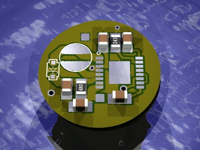
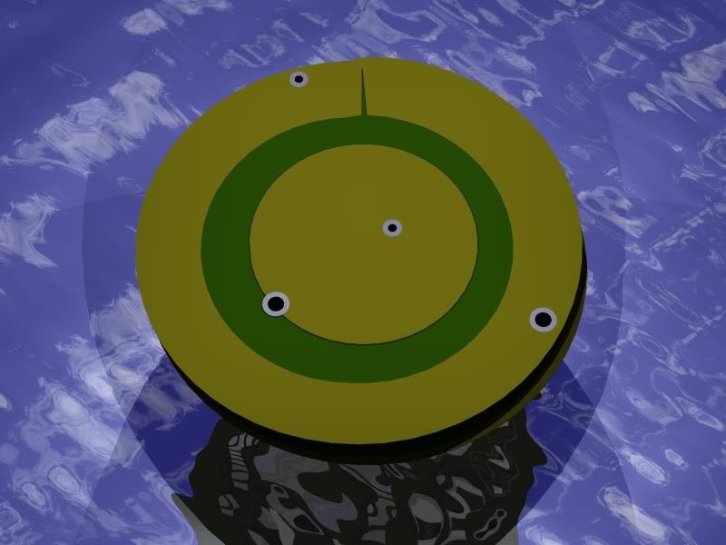
Anyway, this has lots of promise") I'll keep you updated. I have all the parts on me, just need to wait until I can get a couple of boards made... then I can do some final tests and get them scoped.
I'll keep you updated. I have all the parts on me, just need to wait until I can get a couple of boards made... then I can do some final tests and get them scoped.
So... specs?
This version is simply resistor-set current. Nothing special here. However, in a planned V2, it would have an adjustable current pot for 200mA-2A or so, undervoltage protection, OVERvoltage protection, and possibly thermal regulation if I can fit on the board.
I've sourced the parts and everything, and it turns out that I should be able to fit it all on a single, 16.2mm round, one-sided PCB! Theoretically, anyway. Here is the design.
Anyway, this has lots of promise
I'll keep you updated. I have all the parts on me, just need to wait until I can get a couple of boards made... then I can do some final tests and get them scoped.So... specs?
This version is simply resistor-set current. Nothing special here. However, in a planned V2, it would have an adjustable current pot for 200mA-2A or so, undervoltage protection, OVERvoltage protection, and possibly thermal regulation if I can fit on the board.


