Welcome to Laser Pointer Forums - discuss green laser pointers, blue laser pointers, and all types of lasers

Buy Site Supporter Role (remove some ads) | LPF Donations

Links below open in new window

FrozenGate by Avery

Why don't we use op-amp current sources?

Joined
Feb 1, 2008
Messages
2,894
Points
0
I was reading this: Current source - Wikipedia, the free encyclopedia

And after looking at figure 6, I was thinking about running over to the rat-shack to pick me up a few parts to try it out.

It just looks like a very easy current source based on an o amp with a feedback for regulation. What do you guys think? Why haven't we seen more of these around the forum?

Op-amp_current_source_with_pass_transistor.png


Because that's basically what LM317/1117/350 etc are, just all that in one package which saves space.

If you want to give it a go, sure, but after all when it comes down to it, it's much better to just use an IC with all this already inside, can save you a lot of space inside a laser host when it's needed.
 
Oh.

I saw that you can add a transistor to the output of the amp, allowing for much more current though, is that right?

The lm317 is not quite so expandable is it?
 
maybe instead of heating the whole circuit with ~1amp of output, we could heat 2~4 separate output transistors, allowing a bigger output current.
 
It's not the heatsinking alone that's important for greater current capability, it's the elements alone, just because you would heatsink one component greatly does not mean you can get more current through it.

It depends on how it's built.

In either way, you're complicating things which should not be complicated.
 
Who said we don't use them ? ..... at least half of mine are sink or source drivers, and at least 99% of the green modules ones are the same .....

;) :D

Also, mosfets are much better than transistors as power elements ;)
 
I see.

So if for instance, I had one IRFP250 lying around, :whistle: I could make an op-amp driver that could be set for something like... 55 Amps?
 
I see.

So if for instance, I had one IRFP250 lying around, :whistle: I could make an op-amp driver that could be set for something like... 55 Amps?

NO ..... first, cause the IRFP250 is a 200V 33A max mosfet, and second cause, also if it was 55A, it's still an 85milliohm RdsON unit (very good for different applications, anyway)

But you can use it without problems for a 15A or similar currents driver, if you respect the power dissipation factor and heatsink it good ;)

for a 55A driver, assuming you need it for a laser diode, so low voltage, you can use one (or better two in parallel) Hexfet, or also better TrenchMOS power mosfet ..... If you can find an IRF2804S, they are extremely good for these applications, they can hold a maximum of 160A at 40V max, with an internal RdsON of 1.6 milliohms (but remember the power dissipation, a D2PAK package can dissipate max 300W in forced cooling condition, but is always better not go over 100 or 120 W, also with a good heatsink ..... or place 2 of them in parallel) ..... also good is the IRL1404P, this one is in TO220, more common package and easy to use, still 160A at 40V max, with an RdsOn of 4 milliohm ..... but TO220 can dissipate max 200W in forced cooling condition, so is recommended to use at least two of them in parallel with a good heatsink (anyway, the advantage of the mosfets is that they can be directly paralleled ;))

Anyway, remember that for 55A, you also need a Rsense that can dissipate the related power ..... assuming the driver will never used for less than 10 or 15 A (otherwise it don't have too much sense), you can minimize the power dissipated from the Rsense using a constantane bar resistor of 0.05 ohm (more than other, a high current shunt for amperometers :p) ..... this give you a dropout voltage of 2.5V for 50A of current, with a dissipation of 125W on the resistor, so a common resistor is a no-no (or, better said, is a "don't-even-think-about-it" thing :p).....


EDIT: @Bionic-Badger: yes, you're right, i'm too used to considerate "transistors" only the bipolar ones, so never specificate it ..... ah, well, i'm too old :p :D)
 
Last edited:
im using a similar circuit with IXTH230N085T (rds4.4 mOhm idmax 230amp pmax 550w). the power supply i build is adjustable from 1.40volts to 4.60volts and the current is adjustable from 0.0amps to 120.0amps. with a copper heatsink and forced air-cooling.
 
^ I hope you're using the TO3P case, that can dissipate better and more power than the ones in TO247, and also that you are using a pair of them in parallel (the junction can hold 230A max at 25C, but the leads are rated for a safe current of 75A contitnous) ..... anyway, that mosfet is a very good "mule", about current capability.
Only keep the temperature controlled, cause as in any power mosfet, the maximum current depend from the temperature too (It hold the 230A and can dissipate 550W max, but only if kept at 25C, if you left it work around 90 to 100 C, you need to reduce the values of almost half, for long time usage)

Just for curiosity, what are you using as Rsense ? ..... the current shunt of the amperometer ? (at those currents is the more cheap solution, usually)
 
So finding an Rsense is an issue then, since it needs to handle lots of power.

I good friend told me that the LM317 IS expandable though.

Is this dangerous?

163421_1560236008647_1317690211_31300314_5411172_n.jpg


Would a P-channel MOSFET be more appropriate for this instead?
 
So finding an Rsense is an issue then, since it needs to handle lots of power.

I good friend told me that the LM317 IS expandable though.

Is this dangerous?

163421_1560236008647_1317690211_31300314_5411172_n.jpg


Would a P-channel MOSFET be more appropriate for this instead?

Huh... that's an interesting circuit. Never thought about using the LM317 in that way.

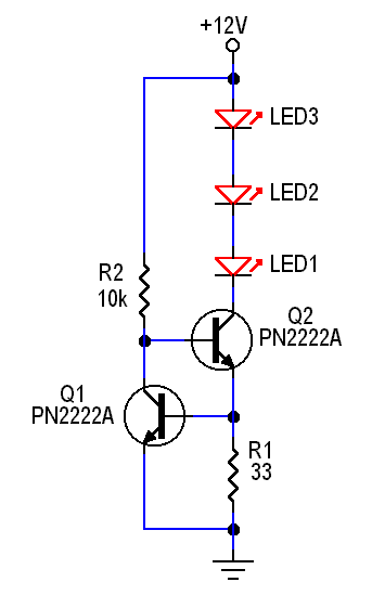
You can also try something like this with a BJT + Pchannel MOSFET without the Rsense.

I've got a driver like this one (N-channel), and it hasn't burnt out my diodes yet. Unfortunately, the image seems down on the page, so scroll down to the image by JTR1962, and replace Q2 with an N-channel mosfet. Note that this is a current sink, not a source. You'll need a P-channel topology for a source.
 
@ Meatball: that configuration is normally used for increase max current in voltage regulators, i don't know if it can work stable without an op-amp based feedback ..... can worth the try, but use a dummy load ;)


@ Bionic-Badger: this link is for a level shifter, not for a current source ..... this one instead can work, but for change the current, you still need to change the R1 value.
 
So finding an Rsense is an issue then, since it needs to handle lots of power.

I good friend told me that the LM317 IS expandable though.

Is this dangerous?

163421_1560236008647_1317690211_31300314_5411172_n.jpg


Would a P-channel MOSFET be more appropriate for this instead?
An opamp with a mosfet works better then a LM317, with an opamp you have more control over things like the voltage drop over the sense resistor.

Your schematic has an error, the ADJ will always be at the output level.
 
Ah, thanks for catching that. This is more like it.

35595_1561618843217_1317690211_31305196_2748639_n.jpg


The thing is, I need to avoid using a circuit that relies on a very high power sense resistor. This is for high currents! 5-20A

So if I took this current sink circuit,

LED_Driver_1.gif

and threw in an N-channel MOSFET, it would look like this:

162712_1561661884293_1317690211_31305313_4465052_n.jpg


Now with an IRFP250, a current of up to 8A, and a supply voltage of 12V, the resistor would STILL be dissipating lots of power... wouldn't it?

Now there ought to be about 2.3-3.0 Volts dropped across the diode, so that leaves a max of 9.7 dropped across the FET and the resistor. So 8A through the FET's .085 Ohms would be .68V dropped by the FET, and then (I'm just guessing at all this really) I get stuck from here.

The resistor's value will somehow determine the current setting, assuming the Vin is constant. And not knowing the resistor's value, I won't know how much power it needs to dissipate.

Its times like this that I wish I were properly trained in electronics.

This circuit is coming along I guess.. just slowly is all!


Back
Top