Welcome to Laser Pointer Forums - discuss green laser pointers, blue laser pointers, and all types of lasers

Buy Site Supporter Role (remove some ads) | LPF Donations

Links below open in new window

FrozenGate by Avery

Why don't we use op-amp current sources?

You can try a modified version of the fet type driver, that i designed years ago for leds ..... but be careful and do some tests, first, cause i had designed this version only for use it with LEDs, and also if it worked good with LEDs, i never tested it before with LDs.

I've hooked up a similar design to a laser diode and it works just fine, though it didn't have a capacitor or the indicator LED.


At low current, LEDs acts as discretely precise voltage references (i forgot to say, use a red led), and in this configuration it "add part of the voltage" (don't know how to explain it better in English, sorry) needed for turn on the transistor, lowering the needed dropout on the RS.

But probably you need to play with the 100K resistors for get the better value.

It was an "on-the-fly" experimental build, at that time, for power a big LED wit a FV of 3.4V with a single Li-Ion cell, not a specific driver for laser diodes, anyway :p

(I suppose that one of these days i need to find enough time for convert my schematic archive in a "humanly readable" form and make an album with them ..... maybe .....)
 
I just tried using an IRFP250 based sink circuit, with 5V input.

At 5A, the FET gets VERY hot. At 12V input, even hotter! I need a bigger heatsink!
 
Last edited:
^ This is normal, remember that all the voltage that you don't need must be turned in heat and dissipated from the mosfet, when it work as regulator (energy can't disappear ;))

Is for this reasom that, usually, is better to use power supplies just a bit more high than the needed FV of the LD ..... like, 5V if you use it for an IR or red diode, or 8 / 9 V if you use it for BR diodes, or similars.
 
Sorry, maybe i'm misunderstanding, but this is the basical configuration of the sink design, already ..... or you are referring about sources ?

You're getting it right. I was refering to the very first post where there is a circuit diagram of a current sink. That shows a bipolar transistor as the current passing element, but that could also be a fet.

As for voltage references: I often just use 1n4148 diodes with 1 to 10 mA bias current. These are quite reliable, although the reference voltage will drop with temperature rises. I suppose this is better then the opposite where the reference voltage climbs with temperature and you get runaway problems.

If you want your current to be really stable just use a proper voltage reference. Those come with under 10 ppm/K thermal coefficients if you want to.
 
Uhm, i think is the same basical circuit i've always used, then ..... 431A as voltage reference, and a mosfet as active element.

http://laserpointerforums.com/membe...ink-analog-modulable-laser-diode-driver-p.jpg

It's a basical schematic for a sink driver, that i use from years with no particular problems.

For source drivers instead, i'm a bit stucked on the problem of high currents ..... til less than an ampere, there's no problem, i've used the second op-amp as "follower/separator" (whatever you call it in English :p) for get the voltage drop on the resistor and drive the first one, and used a dual full common-rail op-amp 272C, and a P-mos for the power element ..... and a "dirty trick", placing a second low value resistor in serie with the mos, so it cause enough difference of voltage for not require a negative power supply ..... but the driver become unstable at high currents (and the second resistor need to dissipate power too) .....

Any idea about how to solve this also for high currents ? ..... the voltage difference is needed, otherwise the mosfet don't work (or this, or a separate negative power suply) ..... also thoughd to use one (or two) power schottky diodes, in place of the resistor, but still they cause more drop than a normal sink configuration ..... don't know if the problem can be solved easily, anyway ..... :thinking: :confused:
 
I think this is a problem difficult to solve really. Constructing source instead of sink drivers poses numerous practial problems, and probably will involve driving one or more of the componets beyond rated specs.

As for the sink design you linked: be careful with that, since excess voltage on the modulation input can drive the output current beyond specified limits quite easily. Also, i don't see any use for the 1k/47pF combo in the return loop, or the 10k resistor in the + input lead of the opamp.

I suppose your aim is stability: if so, run te supply voltage through a small resistor and decoupling capacitor to the actal opamp. I wsould suggest a 1 ti 10 ohm resistor and a 100 uF cap if you have the space to fit them.
 
You're right, that schematic is a generical sink driver with the possibility to be modulated, i have others, but i need time for convert all the "better" ones in a readable form (my "archive" is a pair of cardboard boxes filled of piece of papers with any type of schematic i've designed in my 21 years of work as prototypes designer, plus the ones i made for myself for hobby, and all in a form that require at least 2 translation passages for be "humanly-readable", due to my "perfect calligraphy" and "drawing skill" :p :D)

The components you mentioned are for decoupling and improving stability with not perfectly "clean" power supply ..... and yes, there's one also with a zener diode in the modulation path and decoupling for the op-amp power supply, but is a "lab style" version, where this one can work with lower voltages, like a battery (the "lab" one requires at least 6V, instead, for be stable in all the conditions)


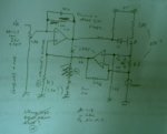
EDIT: just for give you an idea about what i mean, with "humanly-readable", the attached one is the base of the source driver circuit that i'm trying to improve ..... it's the 4th time that i redraw it, and it's cleaned a lot, compared with the first design, so it's "almost readable" ..... i left you imagine how the previous ones was drawed :p :D

EDIT2: damn image not loaded :p
 

Attachments

  • schematic.jpg
    schematic.jpg
    27.5 KB · Views: 578
Last edited:
Hehe.. i know what you mean, sometimes i end up with circuit diagrams that look like completely random doodles :D

I have to properly draw some schematics too - not a fun job to do though :(


Back
Top