Welcome to Laser Pointer Forums - discuss green laser pointers, blue laser pointers, and all types of lasers

Buy Site Supporter Role (remove some ads) | LPF Donations

Links below open in new window

FrozenGate by Avery

Tiny RGB

farbe2

Well-known member
Joined
Oct 3, 2018
Messages
314
Points
63
Hello Guys,

I am working on a new project.
Lets look into:

tiny RGB
I already posted some teaser pictures in a different thread. Because some people have shown interest in RGB in general, I wanted to give you some sort of build log. It wont be complete but it will at least show progress.


First of all, what's tiny RGB ?

Its a small single mode RGB laser pointer with beam correction, integrated battery and USB-C Charging port.
It got:
  • 185mW 638nm / 120mW 520nm / 120mW 450nm Diodes - roughly 400mW of neutral white output
  • tiny 1,5mm round output beam diameter with under 10mm beam at 10m distance - DPSS like
  • 2Wh of integrated battery - good for roughly 45min of lasing at full output
  • Full color Display and D-Pad as a userinterface
  • Full analog modulation with 10bit color depth for amazing fades and colormixing
  • configurable 5mW output limit - safe mode to use without goggles to enjoy the colors
  • Over temperature protection for battery and laser diode safety

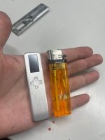
How tiny is tiny ? Take a look for yourself:
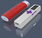
signal-2024-01-28-180531_002.png


Lighter sized is tiny !
81,25mm long, 19,5mm wide, 12,5mm thickness.

Thats it for now, next posts will be the build log
 
Last edited:


Everything started with a idea for a tiny module, so we first need to shop parts.

Let's start with the diodes, the order from eBay and aliexpress showed up quite quickly!
diodes.jpeg

For size reasons, I decided to use 3,8mm diodes exclusively. Everything else is just too big.

Next step: Milling the module, I didn't took many pictures.
module.jpeg

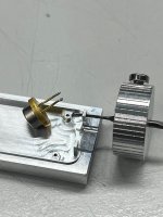
Everything worked out!
On top sits a standard 9mm diode, it was hard to balance the diode ontop, the module is tiny !

Now onto combining the beams! I want to keep some secrets :D so I am not showing the most important part.
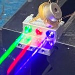
fullyModule.jpeg
Only that it works :D

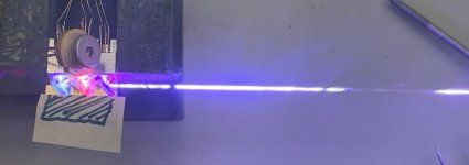
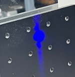
Beam at a distance of 15m fully overlapped.
distance.jpeg

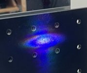
You might ask why beam correcting single mode diodes.
Thats why I want to include beam correction. The beam isn't round but oval shaped with one axis clearly much wider.
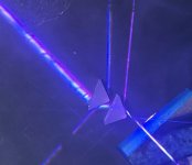
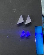
prisms.jpeg

Prisms for the rescue! They expand the slow axis of the laser beam (bottom right is input beam) and therefore decrease the divergence significantly!
You can also see the splitting of the RGB beams, thats a non issue because I just need to readjust the overlap. Didn't do that for this picture.

distance2.jpeg

The beam is now much smaller and almost perfectly round. There is still some noise around the beam wich will be cleaned up in the final unit.


However the 5mm prisms are way too big to fit my desired size goal.
Some diamond grinding and glass cutting later:

prisms.jpg
Much better!

This finishes the module in my self inflicted size constrain and gives me the GO for milling!

Next posts will be housing related!
 
Everything started with a idea for a tiny module, so we first need to shop parts.

Let's start with the diodes, the order from eBay and aliexpress showed up quite quickly!
View attachment 77241

For size reasons, I decided to use 3,8mm diodes exclusively. Everything else is just too big.

Next step: Milling the module, I didn't took many pictures.
View attachment 77242

Everything worked out!
On top sits a standard 9mm diode, it was hard to balance the diode ontop, the module is tiny !

Now onto combining the beams! I want to keep some secrets :D so I am not showing the most important part.
View attachment 77243
Only that it works :D

Beam at a distance of 15m fully overlapped.
View attachment 77244

You might ask why beam correcting single mode diodes.
Thats why I want to include beam correction. The beam isn't round but oval shaped with one axis clearly much wider.
View attachment 77245

Prisms for the rescue! They expand the slow axis of the laser beam (bottom right is input beam) and therefore decrease the divergence significantly!
You can also see the splitting of the RGB beams, thats a non issue because I just need to readjust the overlap. Didn't do that for this picture.

View attachment 77246

The beam is now much smaller and almost perfectly round. There is still some noise around the beam wich will be cleaned up in the final unit.


However the 5mm prisms are way too big to fit my desired size goal.
Some diamond grinding and glass cutting later:

View attachment 77247
Much better!

This finishes the module in my self inflicted size constrain and gives me the GO for milling!

Next posts will be housing related!
Great work so far Farbe. Set yourself a real challenge in making one that small whilst maintaining quality.
 
While designing the PCB I ended up with too many LED drivers, I needed one for the backlight of the LCD panel and the IC that was suitable and small had 4 outputs.
Soo I ended up with a new requirement:

I wanted to have backlighted buttons just because :D

Next Step: Starting with the milling.
I started with the "complicated" part. The buttons!

First the Fire button.
Its tiny and needed to have a translucent window.

I again didn't photograph much.
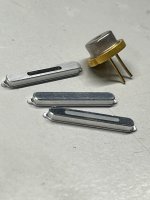
button_finished.jpeg

Again 9mm diode for scale.
I did 3 tries, first, easy without window. Second with window but too small. I settled on the third one.

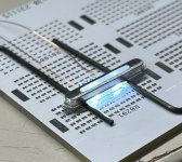
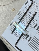
I mocked up some leds to try the translucent window. I only had cold white leds, I will switch to neutral white on the finished PCB.

Button_backlight.jpeg

Button_backlight2.jpeg

It's very hard to photograph tiny shiny parts with just a Phone.


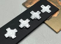
Next on: The D-Pad.

I tried a few designs. Some turned out really bad because the Mill I use isn't the most accurate. I still need to figure out how to improve that.

d-pad.jpg

I also managed to squeeze some backligh-able dots into the last design.
Not sure if I really will go that route. I need to get the PCB to try how it looks.

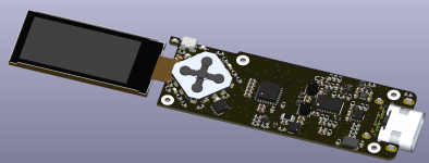
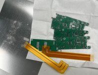
Speaking of the PCB, we have it here:

pcb.png

It's my first time using KiCad and I must say, I quite like it.
The PCB is 18x50mm, features the d-pad, side fire button, all the drivers and the control microcontroller.
It also houses Battery protection and charging.
Its already ordered!
 
Thats incredible! What collimator lenses are you using for the diodes, the block they are mounted in is tiny so I can only imagine the lenses are super small too. Also, how did you go about lining up those dichros? Do you hold them with the lasers aligned and wait for them to set or do you have some sort of external lens holder for micro adjustments? The alignment looks really good.
 
Lets do an update!

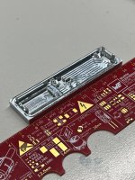
I made the tiny top housing half.
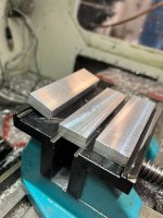
I started by cutting 3 raw 6060 Aluminum bars.

3bars.jpeg

Why three?
Because its easier to run a CNC toolpath multiple times with the tools already set up than to mess a part up at a later op and need to setup all the tools again!

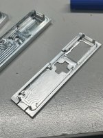
I started with the inside pockets. That went quite smooth.

firstside.jpeg

Lets cut some threads, they are tiny!
If you are afraid of cutting threads, the next picture isnt for you. M1! 0,75mm tap drill diamater.

threads.jpeg


Next op is thinning the plate and rounding the corners.
Disaster struck!

disaster.jpeg

The part did come loose and the cutter just shreded it.
Thats why i cut multiple blanks!

After adjusting the toolpath to lower the preasure on the part, the next one went fine.

luck.jpeg

Turned out quite nice!

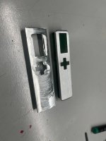
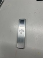
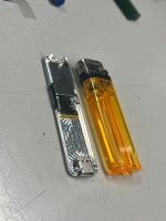
Now with display and d-pad.
Did i mention that this thing is tiny?
display.jpeg
tiny.jpeg
back.jpeg

Lets hope the PCBs will arrive soon!
 
Thats incredible! What collimator lenses are you using for the diodes, the block they are mounted in is tiny so I can only imagine the lenses are super small too. Also, how did you go about lining up those dichros? Do you hold them with the lasers aligned and wait for them to set or do you have some sort of external lens holder for micro adjustments? The alignment looks really good.

Thanks!

The dichros are held by custom mounts that are adjustable. They are not glued in place.
The lenses are 2,85mm diameter with a focal length of 2mm.
It gives me a tiny 0,6x1,25mm beam. All the colors are slightly different but the difference is so small that it doesnt matter.
The prisms will then expand the small axis to the same diameter as the big axis.
 
Thats a masterpiece, that fact you can adjust those dichros on such a small assembly is mind blowing
 
I always end up with some small cuts, while machining. Freshly milled surfaces have very sharp burrs that can easily cut you.
Cutters are also very sharp.

However the red dots are just permanent marker, no blood included in these pictures :D
What’s work without blood, sweat and tears.
 
Are you a metal turner?
I do everything thats needed.
Turning only manual and milling, manual and computer controlled.
So far, I only used the mill for this project. I cut the blanks with a manual mill and than finished by CNC milling all the features.

Tools for the lathe and the mill are sharp enough to shave. But it certainly depends on what you cut.

Tools made for cutting steel are usually quite blunt. They are more like "scraping" the material away.
But for aluminum (which is mostly what i do due to weight and thermal conductivity), cutters are sharp like craft knifes.
One wrong move and a carbide aluminum endmill will slice you open. Not so much on coated steel endmills or heavyly used ones.
 
I sometimes grind my own tools for special shapes out of HSS.
But i only use carbide for milling cutters.
Its much more ridgid especially for small endmills.

Milling is often done with cooling and cutting fluid that helps remove heat and washes the chips away to keep the cutting area clean.
Tools also keep their edge much longer.
 
This is insanely impressive my friend!!
Great job!
I would LOVE to collab with you on a larger unit, if you are interested :)
 
Last edited:
Great work as always, farbe2.
Just when I think my machining skills are improving, you come along and show off again.

I'm curious about your treatment of the prisms. Did you grind and then re-polish one of the optical surfaces?
I don't see how you could achieve that size without doing so.


Back
Top