- Joined
- Jul 10, 2015
- Messages
- 13,115
- Points
- 113
Have you ever aligned cylindrical lens pairs to reduce a MM diodes divergence ?
----edit----
----edit----
Last edited:


Follow along with the video below to see how to install our site as a web app on your home screen.
Note: This feature may not be available in some browsers.


Have you ever aligned cylindrical lens pairs to reduce a MM diodes divergence ?
Imagine doing that in a hand held build that incorporates a beam expander and you will understand why the starting beam needs to be centered to match the beam expander, like I said if not using the beam expander and your corrected beam were to exit 2 degrees off center it might not be noticed, but fed into a beam expander that's attached to the host with a difference in alignment and you will see it.

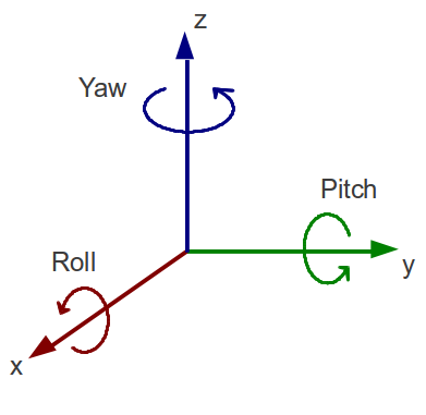
A few things can cause the beam to exit off axis.
A. The collimator lens could have some degree of tip or tilt. Good machining can solve this problem.
B. The most common is the emitter is not concentric relative to the lens. This can be solved by shifting the diode X or Y relative the lens.
C. The die is actually misaligned with the diode body. Most spec sheets give the max degree of misalignment allowed. Centering the diode to the lens will make the beam exit straight just displaced by some amount.
Almost all beam alignment issues can be solved by just moving the diode X or Y.
First of all, the emitter is, for our purposes, a straight line and therefore, can't be concentric to anything. Concentricity concerns how one circle corresponds to another circle. If they aren't concentric, the they are eccentric. This is where some parts of the circles are not aligned to one another.
Secondly, if the die is not centered in the focusing lens, this is not an angle adjustment, but a position adjustment. If it is close, and many are, then it makes little difference and the beam will exit the lens in the center, or close enough to it that it won't matter. These angle adjustments are in addition to position adjustments and should not be confused with position as you will soon have a mess in trying to align one with the other.
Hardly anyone gets the emitter exactly in the center of the focusing lens, so close is all one can hope for. It is called tolerance and is a measure of what you can get away with. And yes, in this case "close enough" can work as the exact center is basically unachievable. If your link is trying to show something you have not already stated, you need to fix it. I cannot see it. :thanks:
My suggestion for those that want to use correction optics, is to get away from the pressed in type mounts. A simple mount that allows the diode to "slide" X, Y on the rear face of the mount is all that's really needed. And .001mm resolution is easy with only "bare hands". This type mount is pretty standard in projectors. Maybe someone needs to make one for handhelds.
My suggestion for those that want to use correction optics, is to get away from the pressed in type mounts. A simple mount that allows the diode to "slide" X, Y on the rear face of the mount is all that's really needed. And .001mm resolution is easy with only "bare hands". This type mount is pretty standard in projectors. Maybe someone needs to make one for handhelds.