

Fiddy
0
- Joined
- May 22, 2011
- Messages
- 2,736
- Points
- 63
G'day,
Been meaning to build this puppy for a while.
I wanted to make a laser like the one seen in the predator movie.

So i found a host that could accept a heatsink big enough for 3x aixiz modules, i chose the TK-35 Fenix copy.

Now what diodes should i use?
I would of liked a LPC-826 or similar 660nm diodes but running 3 of them would cause trouble as they are case negative.
I ended up choosing the Mitsubishi ML520G54 110mW, simply because they are case isolated.
I saw rhd did some testing and killed one at 400mA, so i opted for a safer current at 250mA.
Now how was i going to run 3 diodes at once?
I looked at running 3 separate drivers, it could work, but would cost more than 1 single driver. So i chose a single driver running the diodes in series.
Now the Mitsubishi ML520G54 will run at around 2.7-3V typical.
so i needed a driver that could deliver 250mA @ ~9VDC & the host im using is designed for 2x 18650 in parallel but can run off one with a dummy cell.
The only driver i know capable of such a high boost voltage was the Microboost by Dr.Lava, it can boost to 13VDC, so that is what i chose.
I set by range on the Microboost to 140mA- 280mA.
obviously the Microboost cant output 1A at 13V so there is a formula in the spec sheet that i followed.
(Vout x Iout) ) / Vin < 1.2
So if the power out divided by the voltage in is less than 1.2, the microboost will handle it.
(9V x 0.250A) / 4.2V = 0.53
0.53 < 1.2 = Win!
The maximum current at 9V i could have is
4.2 / 9V = 466mA.
I had bobhaha make a heatsink for me, thanks man!
So now from design to reality.
Here's the plan.
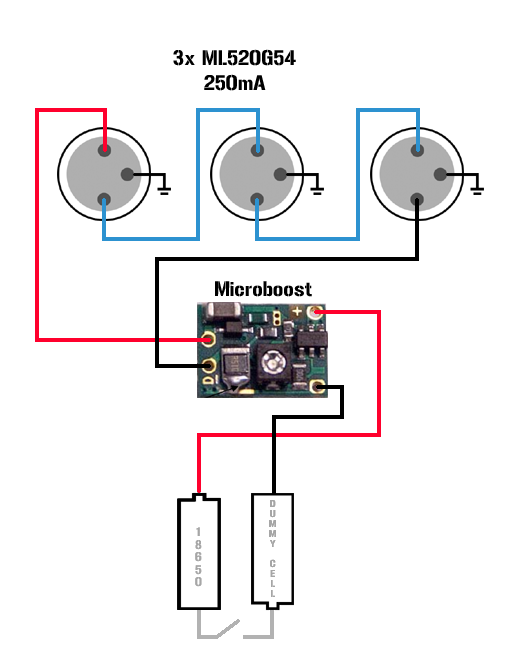
The Build.
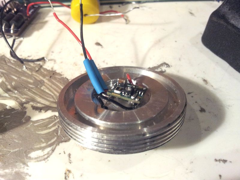
First i set the driver range and current, 250mA and thermally glued it to the pill.
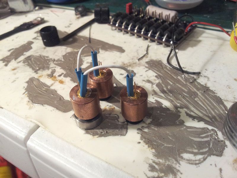
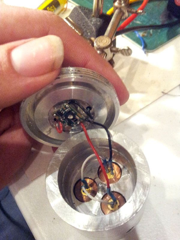
Then i pressed the 3x diodes into copper modules with some thermal paste and joined them together.
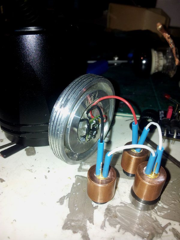
Attached the driver to the diodes.
Installed into the host.
I soldered at wire across one of the battery slots as my dummy cell
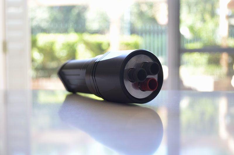
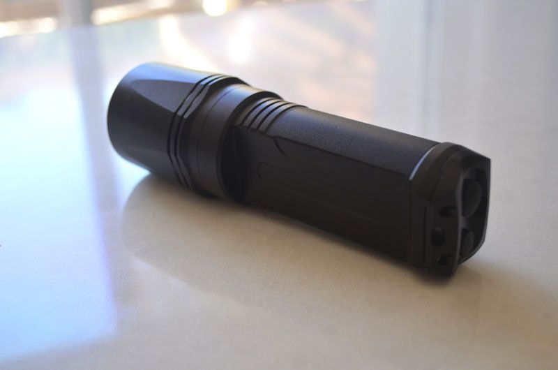
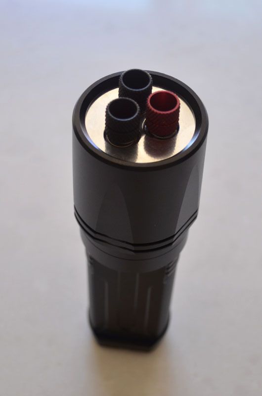
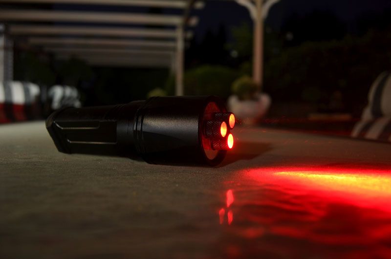
Now it is completed.
LPM for each diode
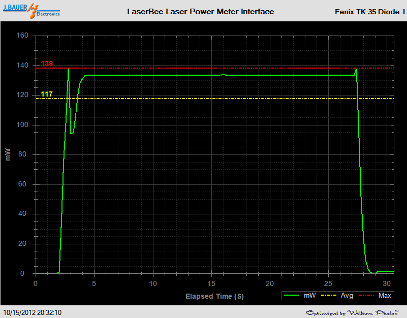
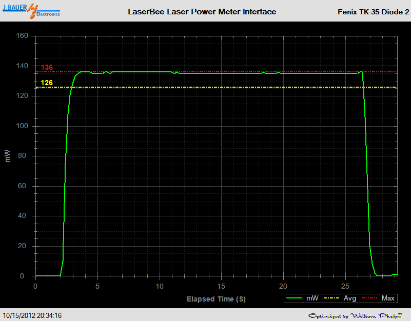
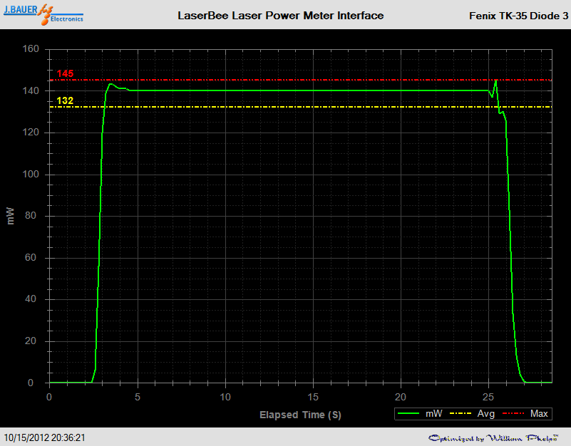
Each diode is within 5mW of each other which is good enough.
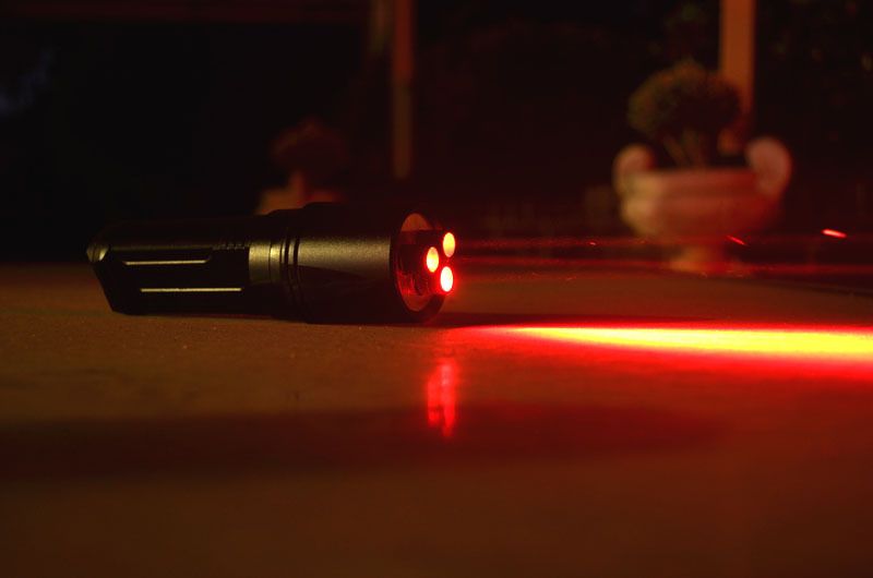
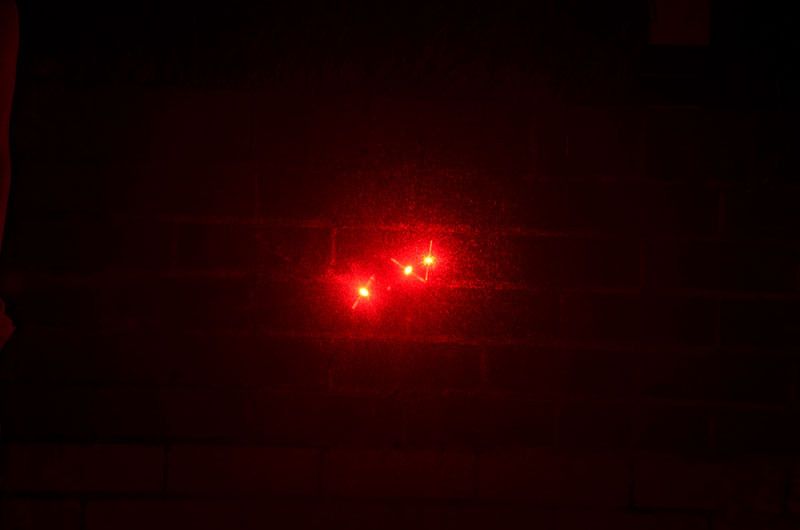
As you will see below, the beams aren't parallel with each other and require some alignment that i have yet to accomplish.
Thanks for looking!
Fiddy.
Been meaning to build this puppy for a while.
I wanted to make a laser like the one seen in the predator movie.
So i found a host that could accept a heatsink big enough for 3x aixiz modules, i chose the TK-35 Fenix copy.
Now what diodes should i use?
I would of liked a LPC-826 or similar 660nm diodes but running 3 of them would cause trouble as they are case negative.
I ended up choosing the Mitsubishi ML520G54 110mW, simply because they are case isolated.
I saw rhd did some testing and killed one at 400mA, so i opted for a safer current at 250mA.
Now how was i going to run 3 diodes at once?
I looked at running 3 separate drivers, it could work, but would cost more than 1 single driver. So i chose a single driver running the diodes in series.
Now the Mitsubishi ML520G54 will run at around 2.7-3V typical.
so i needed a driver that could deliver 250mA @ ~9VDC & the host im using is designed for 2x 18650 in parallel but can run off one with a dummy cell.
The only driver i know capable of such a high boost voltage was the Microboost by Dr.Lava, it can boost to 13VDC, so that is what i chose.
I set by range on the Microboost to 140mA- 280mA.
obviously the Microboost cant output 1A at 13V so there is a formula in the spec sheet that i followed.
(Vout x Iout) ) / Vin < 1.2
So if the power out divided by the voltage in is less than 1.2, the microboost will handle it.
(9V x 0.250A) / 4.2V = 0.53
0.53 < 1.2 = Win!
The maximum current at 9V i could have is
4.2 / 9V = 466mA.
I had bobhaha make a heatsink for me, thanks man!
So now from design to reality.
Here's the plan.
The Build.
First i set the driver range and current, 250mA and thermally glued it to the pill.
Then i pressed the 3x diodes into copper modules with some thermal paste and joined them together.
Attached the driver to the diodes.
Installed into the host.
I soldered at wire across one of the battery slots as my dummy cell
Now it is completed.
LPM for each diode
Each diode is within 5mW of each other which is good enough.
As you will see below, the beams aren't parallel with each other and require some alignment that i have yet to accomplish.
Thanks for looking!
Fiddy.
Last edited:


")
") :beer: +1
:beer: +1