Welcome to Laser Pointer Forums - discuss green laser pointers, blue laser pointers, and all types of lasers

Buy Site Supporter Role (remove some ads) | LPF Donations

Links below open in new window

FrozenGate by Avery

Tesla Coil Build Thread

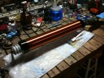
I'm having so much fun playing with this mini tesla (1.5 inch arcs) I can't wait to finish the bigger one (14" tall). The problem is the high frequency interferes with my moms digital TV waves so she keeps complaining.
Are there any cool experiments to try with it?
Also, I'm gonna be now building more caps. Monday is recycle day here and people throw out tons of jars.

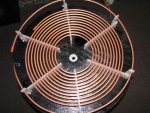
EDIT: Is 10 gauge wire thick enough for a primary? My dad has 50' of 1/4 copper tubing, but it's his and I'm not allowed to use it.

And also, what would be the best configuration for a primary? How many winds do you think is good to start with? Should it be insulated wire or non-insulated wire?
How far apart should the primary wraps be?

Try some different toploads and a clear light bulb
play with tuning each time


I can't see my post. Anyways, today I got a 120 watt ballast, orginally thought is was 80 watt, and the flyback now produces white/blue arcs of over 3 inches! Sometimes over 4 inches if the arc is vertical.
The new problem is corona forms in the jars from this higher voltage. :) :tired:
What would be the solution? Is this too much voltage for a Tesla Coil input? How many volts is 4 inches of arc. Does this depend on current too?
Also, I hear it's bad to directly view the spark gap without welding goggles. Is this true also for the flyback arcs?

Nice find on the 120w!

The corona will get you massive losses. Also high frequency passes through glass which is what your Layden jar's dielectric is made of. Either use an NST for 60hz(lol I know you hate hearing this) or get a professional capacitor made for rf.
 
Last edited:
As noted above, the AC component of the input waveform (which is actually the output ripple of the flyback) suffers huge losses through the glass dielectric of home-made capacitors. What you end up getting at the output is the DC bias level below the ripple troughs. Corona losses are in addition to these dielectric losses.

Upaa27 is spot on with his reply above.
 
You don't need a welding mask unless it's
so bright you are being blinded by it. UV
sunglasses or even polycarbonate safety
glasses will block any dangerous UV.

Getting bit by the HV is far more dangerous.
Don't ever work alone.
 
Ok. So if rf frequencies are the problem, are there any type of home made capacitor I can make that doesn't have much loss? Loss is the problem, and if I can use plastic or plexi glass caps, that would be better than nothing. I'm trying to make all this minial cost, I saw a guy who made a 250,000 volt one from trash-EVERTHING WAS FROM THE TRASH!!!

Anyways, yes I measured the voltage and current, using several meters my dad has. 44kv max. I measured 32kv at 4ma, which is strange, because this is more than the ballast is rated for.

I've also gotten as high as about 20ma but the arcing wasn't much gap. Using different electrodes.

My grandfather has an osilloscope which showed the frequency of the flyback was about 28khz.

Arcs easily light plywood on fire. I never knew how much of a fire hazard hv was until now.

This new setup was arcing across the pins so I used hot glue rather than oil to insulate them, It seems

to be working fine.
 
If you can find thick transparency sheets (polypropylene) you can make a stacked capacitor out of them using heavy duty aluminium foil. You'll still get coronal losses, but that dielectric is relatively low loss at RF (it's what is used in professional caps).

Oh, and most voltage claims with TCs are false. Because it is high frequency RF (hundreds of KHz typically) the streamers are much larger than what the voltage if DC would produce. I.e. experts have determined it takes ~50kV to achieve breakout from a standard torus' radius of curvature, and while increase in voltage goes increase streamer length, it is nonlinear and streamer growth mostly depends on plasma channel dynamics, not topload voltage. A 180kV output can yield 6 meter long streamers, where as if it were only DC it would only be a 180mm long spark.
 
Oh crap, today I burned out the coils secondary. No continuity. Should I try to remove the core and wrap wire on it? Would it still work with the ballast?
 
By coil you mean the flyback transformer, right? You can reuse the core for a low voltage inverter, but "it's dead, Jim". (reference, not literal).
 
:facepalm: Usabro, FP wasn't replying to you, that's why he quoted Nospin.

FP, I do believe that is Nospin's coil in his signature.
 
:pop: by all means continue. I'm learning about fly backs.

Well for me I learned , just shove as much power in as possible and see what happens : P , best way to drive them is with a fixed frequency half/full bridge at 25 or 15Khz ( depending what the flyback was from ) or a ZVS ( frequency can be adjusted by varying tank capacitor with a fixed turn primary , lower turn primaries result in higher voltages at increased power draw but require larger tank caps for lower frequency's )

I haven't used any for TC use as Ive only made VTTC and SSTCs but even flybacks on their own with a half or full bridge give good displays

Even better when ya add FM modulation , in this case I used a 4046 with NPN preamp to give more VOC frequency swing .

https://www.youtube.com/watch?v=YzdWguOHDwA&index=16&list=UUvjDVNxRU2DInDMQQw_iYJA

https://www.youtube.com/watch?v=M9c7hjhYNq0&list=UUvjDVNxRU2DInDMQQw_iYJA

:D
 
Last edited:
Wow is that your coil Nospin ?

Yes Flaminpyro that is my Museum quality TC

https://www.youtube.com/watch?v=5XVRtoRkVW4

https://www.youtube.com/watch?v=_WqFPIJPgoI

The first is a run with 18" fluorescent tubes is wood blocks to make it more interesting
The second was one of the last runs in Mad Scientists lab before it got to wild!

This is from 4 years ago

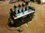
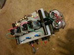
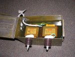
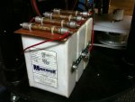
The PS is based on 2 MOT's in series inside of a military ammo can submerged in oil feeding a half wave rectifier charging a 83nf Maxwell cap bank that is fired with a 7" single rotor 4 pole rotary spark gap into the 6 turn primary 1" coupled to the 4.25" secondary and that charges the 6x24" topload

with that setup I consistently achieve 60" white bolts

I am upgrading this month to a 6.6" secondary and a 8x30" topload
with a goal of 80 inches arc

Here are the build pics:
 

Attachments

  • IMG_0539.jpg
    IMG_0539.jpg
    79.5 KB · Views: 447
  • IMG_0540.jpg
    IMG_0540.jpg
    78.8 KB · Views: 310
  • IMG_under oil.jpg
    IMG_under oil.jpg
    107.8 KB · Views: 1,772
  • IMG_0501.jpg
    IMG_0501.jpg
    60.7 KB · Views: 170
  • IMG_0470.jpg
    IMG_0470.jpg
    78.7 KB · Views: 175
  • IMG_0352.jpg
    IMG_0352.jpg
    109.8 KB · Views: 343
  • IMG_3114.jpg
    IMG_3114.jpg
    43.4 KB · Views: 278
Last edited:
USAbro,

I know someone who made a coil about 2 years ago with a tank cap consisting of salt water and many soda Bottles and powered by a 4 kv 60hz nst. They estimated 1 million volts but the arc length said 700kv. A little over 2 feet arcs! Not too bad for a crude sgtc eh?
 
Last edited:


Back
Top