Welcome to Laser Pointer Forums - discuss green laser pointers, blue laser pointers, and all types of lasers

LPF Donation via Stripe | LPF Donation - Other Methods

Links below open in new window

ArcticMyst Security by Avery

TEC Cooling


Joined
Jan 2, 2009
Messages
11,800
Points
0
My plan is to hook it up to a small heat sink holding an aixiz module with a 120mW PHR.
 

HIMNL9

0
Joined
May 26, 2009
Messages
5,318
Points
0
Sorry, but why just don't use a simple NE555 in semi-PFM configuration, for stabilize the TEC with an NTC as feedback ?

I know that it's not designed for this specific use, but i always used it in this way, and it work well enough :p
 
Joined
Jan 2, 2009
Messages
11,800
Points
0
Sorry, but why just don't use a simple NE555 in semi-PFM configuration, for stabilize the TEC with an NTC as feedback ?

I know that it's not designed for this specific use, but i always used it in this way, and it work well enough :p

:thinking: HUH?

I think you guys are giving me to much credit in the electronics field. I work very well with my hands. I can build/modify anything. But anything beyond basic wiring, I'm a n00B.
 

HIMNL9

0
Joined
May 26, 2009
Messages
5,318
Points
0
OOPS ..... i'm sorry, i'm so used to chat with friends that have basically my same hobbies (mainly electronics), that always tend to suppose that anyone already know what i'm saying ..... my guilty, apologise.

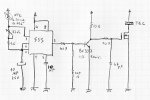
Here is a basical schematic that i use in some applications with small TECs for regulate the temperature ..... it's a 12V version, and it's optimized for my specific use, so maybe you need to try to change some values a bit, but it's a good and stable enough base for start to experiment (well, if the inventors of the NE555 see my schematics, probably they want to kill, me, but hey, they works, so ..... :D)

Sorry, i drawed it in hurry, i'm going home, so it's not too much elegant, but i think it's easy to understand ..... use 470uF/25V and 100nF ceramic on the power supply line (i not drawed them, but is an usual filtering value) ..... the mosfet i'm using are IRFZ serie, you can use any with similar characteristics, and that hold the current needed for your TEC.

Basically it's just a low frequency (from half second to 2 / 3 seconds, depend from the temperature of the NTC) pulsed driver with a big difference in variation between the ON and the OFF times of the cycle ..... the NTC is a common miniature element, with 10 Kohm value at 25 C, but you can use different ones, i use these ones just cause are the more easy to find around here ..... it switch on and off for short periods (approx half second) the TEC, and when the temperature drop, it just elongate the pauses between the pulses, til it stabilize ..... and when the temp rise again, it short the pauses, giving more power to the TEC.

If you have a fixed voltage TEC, you can just attack it directly to the circuit (as example, TECs built for regular use at 12V, can work without regulation, with the circuit powered at 12V) ..... if you have TECs with different voltages, or you give a different power line to the TEC, or, better, just use this circuit for power up a voltage regulator that can feed enough current to the TEC (like, if you have a TEC rated for 5V 2A, you can use the circuit for feed a voltage regulator that then give the 5V 2A to the TEC)

attachment.php
 

Attachments

  • TEC driver 01.jpg
    TEC driver 01.jpg
    151.5 KB · Views: 5,147

Krutz

0
Joined
Nov 21, 2007
Messages
1,733
Points
48
great! thank a lot for this, bookmarked!
didnt find such an easy and small solution yet, rep+1!

manuel

edit: cant rep you again? dammit..
 
Joined
Nov 22, 2008
Messages
1,267
Points
38
If anyone builds the schematic that HIMNL9 posted, would you be so nice as to post a pic of the end result?... for those of us that are not electronically inclined to be able to interpret schematics. With a pic and schematic posted it should be a lot easier to understand. Thanks!!
 
Joined
Oct 22, 2009
Messages
83
Points
0
I have two 100W thermoelectric coolers. Most work at 12V as they are mainly designed for cooling computer components. If it says on the TEC what it's maximum wattage is then divide the wattage by 12 to get how many amps you need from a power supply. (searching peltier device in google will get better results)

They are simple to set up.

For instance my 100W TEC uses 12V.
So 100/12= 8.3A
So i need a 12V 8A power supply

Get the polarity right or it will heat something up xD


(Sorry if this has already been explained, i quickly looked through the posts lol)
 

Things

0
Joined
May 1, 2007
Messages
7,517
Points
0
If it says on the TEC what it's maximum wattage is then divide the wattage by 12 to get how many amps you need from a power supply. (searching peltier device in google will get better results)

They are simple to set up.

For instance my 100W TEC uses 12V.
So 100/12= 8.3A
So i need a 12V 8A power supply

This is simple ohms law, it can be used to calculate the wattage for anything, not just TEC's :)
 

HIMNL9

0
Joined
May 26, 2009
Messages
5,318
Points
0
Hi ColdStl, sorry, i really don't know how a picture of a circuit can be more helpful than a schematic diagram (maybe it's just that i'm too used with schematics), but if it can be helpful, i still have one of these drivers working on my on-the-fly labby unit (is an unit that i use when i have to do "flying tests", so it's always half dismantled), here's some pics

attachment.php

attachment.php

attachment.php


This version have some more components than the basic schematic, cause i modified it a bit in the time, but basically is the same, i just added it a led and a better filtering section with a zener ..... here the NE555 works at 9V, so i can use different current configurations, and the ripple due to the switching of the TECs don't interfer too much ..... and the mosfet is a "hexfet" recovered from a motherboard (is not easy to salvage them in good state, but they're small, and are rated at 27A and 6 milliohm RdsON :p)
 

Attachments

  • tecdriver001.jpg
    tecdriver001.jpg
    244.4 KB · Views: 1,839
  • tecdriver002.jpg
    tecdriver002.jpg
    213.2 KB · Views: 1,811
  • tecdriver003.jpg
    tecdriver003.jpg
    193.6 KB · Views: 1,680
Joined
Nov 22, 2008
Messages
1,267
Points
38
Hi HIMNL9, thanks! The schematics, together with the pics, makes it a lot easier for me to figure out. This looks a tad more complicated than the DDL driver, but still very accomplishable for someone as electronically challenged as myself.
 

Krutz

0
Joined
Nov 21, 2007
Messages
1,733
Points
48
..post your results, coldstl! :)
..and dont forget, you only grow with things new to you! :)
good luck, people will gladly assist you if you get stuck at some point!

manuel


Top