Welcome to Laser Pointer Forums - discuss green laser pointers, blue laser pointers, and all types of lasers

Buy Site Supporter Role (remove some ads) | LPF Donations

Links below open in new window

FrozenGate by Avery

TEC cooled Diode testing station, suggestions?

Hey guys, sorry for double post:

I had another question, I was browsing ebay, and the smallest LCD panel ammeter I could find was This.

The problem is it's resolution is only 0.1A. Any suggestions on any modifications I can make to the input (I.e. measuring current through a certain component) to magnify the reading the ammeter gets (so the ammeter would read 250mA as 2.5A, etc).

But even still that would be a discomfort... Does anyone know where I can get an LCD ammeter that is like +-1A max and 0.001A Resolution?

Regards,

amk

EDIT: lol nvm I guess they are all listed as "AMP meters" on ebay not "Ammeters"
 
Last edited:


So I went ahead and also bought this Volt meter and this Ammeter for measuring the current being pulled by the diode and the voltage across the input of the diode.

My paypal PayLater maxed out tho... so I had to pay for the volt meter by e-check >_<. Should take some time to process/arrive.

So, any of you LPM experts know if I can throw together a circuit to graph mA, V(diff), and mW (output from LPM circuit as mV)? I have the knimrod LPM interface for graphing mW vs Time graphs, but I want to incorporate mA and V on the same graph, or maybe even mW vs mA, etc.

Any way to modify knimrod's circuit, or maybe even make a totally new one?

Regards,

amk
 
Did I show you this diode test set-up I make them in 3.7mm,5.6mm and 9mm sizes.
9sbgn7.jpg


May I ask why are you wanting to run a TEC in the first place, are you planning on running 630nm diodes ? or very high power diodes ? even for long runs this heatsink with a small fan is good for continious use up to 5 watts easy. after that you will be going to "C" mount anyway.
If you are going to run a TEC and do it efficently you will need a "feed back loop" that sens the temp very close to the edge of the laser diodes can this tells the TEC's regulater how much current to apply to the TEC. other wise just appling 5 volts to a TEC my or my not be enough to realy do what you are suggesting.
Please don't get me wrong I'm not trying to rain on your parade it's just a TEC seems a bit over the top for testing ?
Good luck...
 
Last edited:
Did I show you this diode test set-up I make them in 3.7mm,5.6mm and 9mm sizes.
9sbgn7.jpg


May I ask why are you wanting to run a TEC in the first place, are you planning on running 630nm diodes ? or very high power diodes ? even for long runs this heatsink with a small fan is good for continious use up to 5 watts easy. after that you will be going to "C" mount anyway.
If you are going to run a TEC and do it efficently you will need a "feed back loop" that sens the temp very close to the edge of the laser diodes can this tells the TEC's regulater how much current to apply to the TEC. other wise just appling 5 volts to a TEC my or my not be enough to realy do what you are suggesting.
Good luck...

I wanted to run TEC so I can stress test and push diodes without worrying about temperature whatsoever, and I decided why not just go overboard and TEC cool it. That and I wanna mess around with TEC, been wanting to for a year or so.

About the feedback loop, do you mean 5v constant mA would be too much or too little? Do I want to run a feed back loop to tell it when to apply more, or to tell it when to back down?

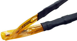
I was looking to do some fancy things with controlled temperature, but I couldn't find a decent thermometer. Back when I was really into overclocking PC's, I used to buy these thermometers with sensors that looked like this:
probes250.jpg


With something like that, I can slip it into the block with the aixis module and everything, and control the LD's temperature somewhat. I couldn't find any standalone LCD thermometers with that sensor though, other than this one, but the problem is I don't need 2 displays, and 80 bucks is a little too much lol.

Basically so far I've got the Thermal LPM with LCD output/Serial output for computer, I(tot) through the LD output to LCD, and V across the LD output to LCD, and Potentially *C of LD output to LCD. Adjustable multi-turn pot with large knob near LCDs for easy adjustment, and of course the LD + Cooling itself. I'm thinking I will need 4 9v's, 3 to power the LCDs one to power the LPM circuit, and maybe some LiPo's for the LD driver circuit itself. I'm still debating what LD Driver to use... And what driver to use on the TEC..

I'm also wondering what I am gonna use to enclose this all... I was thinking maybe having it all in a black box, except for the TEC getup which would slide out or something, as TEC in enclosed space is worthless. I also wanted to be able to maybe have the LPM head glued to the side of the box, then cut out that part and attach it to a hinge, so if I want to just use the LPM sometime I can pop it open and flip it out.

Lots of questions not enough answers! O_O

Thanks everyone,

amk


Hmmm wait a minute, your diode testing heatsink does not require the diode itself to be pushed into anything? Just held in place by that screw?

Can you make this only instead of that round heat sink a smaller more compact copper block?

EDIT2: So for a feedback loop I would be looking at a simple thermistor in the regulator itself, or in series with the Peltier? This way i.e. as temperature goes down resistance goes up, and vice versa?

Edit3: I found a NTC Thermistor on AE, but with the temperatures this TEC is running the thermistor will almost always be at maximum resistance anyways. If it is REALLY necessary, I could always just add a thermometer and a large pot to the control panel, and if I see the temperature go too high or too low I can adjust accordingly.
 
Last edited:
Now you got it all you need is a simple "feed back loop" one resistor with the right tempure coefentient placed in the right spot will control the current going to the TEC through the driver for the TEC, of course you still have a trim pot or an upper and lower set pot and a temp set control pot.


EDIT2: So for a feedback loop I would be looking at a simple thermistor in the regulator itself, or in series with the Peltier? This way i.e. as temperature goes down resistance goes up, and vice versa?

Yes I could make this test heatsink and then mill one side flat to about 1mm from the edge of the diode can, that would give you a wide flat surface aprox 45 x 35mm flat. the rest would still be round and finned.
I think with a TEC you will want the diode as close as poss.
 
Last edited:
You can use machine pin breakaway headers for fast connecting diodes. They have an extremely firm grip and I suspect they're the same ones used in the diode sockets that Thorlabs offers. Not sure how they perform over many repeated connects/disconnects, but I figure you can solder new ones on after that point.

For the TECs, at least with peltiers used for watercooling processors, I remember seeing that people use silicon grease over the pin sockets so that no moisture can get in there when it's finally connected. The pings make a hard connection, so there's no lack of conduction, but the condensed water can't get in. So maybe just coat the back of the diodes with the grease before connecting them up.

For the themometer, you can use the digital one-wire thermometer found here. Just hook it up to a simple microcontroller (like an Arduino board) and you can use the data for temperature compensation, etc. I've used them myself and it is extremely easy to use, spitting out number that I can work into my code.
 
Last edited:
What kind of wattage am I aiming to get out of this device to cool the LD...

Obviously not the full 90W, especially at 5V (That would need like 18A!)...
 
Hey badger, about the logging


Would I be able to use something like this to log the output of the LPM (measured in mV) and other things measured in A or V?

Or would it only work with something like the thermometer you linked?

and finally, how would I work it? I'm not quite understanding, it dumps logs onto its memory in a text file format? I would just take these over to the computer for graphing?
 
What about an Arduino board for the logging ?

So you can log til 6 values, and add all the memory that you need, and also use it for all the outputs, inputs and controls that you want .....

Just as idea .....


EDIT: and if you need more, you can use the "mega" version ..... also if i think that 54 I/O ports and 16 analog inputs, probably, are a bit too much for a LD tester :p :D
 
Last edited:
That logger has 3 ADCs that you can use to connect to analog sensors. The ADCs convert an analog signal (a voltage reading) into a digital reading. That logger will record the values from those ADCs to its memory. However, the thermometer I linked you to is a digital thermometer, which does all the ADC work for you and returns a number which corresponds to the temperature. It's not compatible with that logger because it doesn't return an analog signal.

To use the logger you linked, you can use a temperature sensor like this one. It's a pre-calibrated analog sensor, and actually costs a bit less than the digital one.

One benefit of the board you just linked is that it has three ADCs, so you could hook up one to temperature, another to a current sensor, and maybe one to an intensity logger, so that all the data is read simultaneously.

How do you use it? The board has a power and ground input which you can connect to a 3.3V battery source. I would add an on/off switch to it so you can start/stop the logging. Connect one or more of the ADC pins to the sensor you're using. Power it up, and it'll start recording.

How to get that data off? Buy one of Sparkfun's FT232 boards. It provides you with a USB-to-UART interface that you can use to connect to your datalogger via the TX, RX and ground pins. Basically, you connect the FT232 board to the uLog's pins, plug in that FT232 board to your PC via the USB, and access the virtual com port using a terminal program (see the download links at the bottom of this; Br@y's is a nice one).

The uLog should provide a prompt "?" which you can type "r" (read) or "e" (erase). I'm not sure what the format is, but you'll have the data that you can convert into a graph or something.

One reason I suggested the Arduino + digital temperature sensor is that you can setup a PID loop to control the temperature of your setup to a specific amount without having to really worry about what the specific power you need is. Here's something like that for an espresso machine. The key part is the feedback loop that takes the sensor data to regulate the output of the temperature regulator (your peltier).

You can also use the Arduino to record your temperature data by just outputting the read values as they come in.
 
You can also use the Arduino to record your temperature data by just outputting the read values as they come in.

Well, if he can do a bit of programming, he can probably use one of them for almost anything ..... just as example, one input for the TEC temperature, that drive it from one of the PWM outputs, another for the cycles, another for the LD temp, one for the intensity, with a cell and an op-amp, and so on ..... or i'm wrong ?
 
That logger has 3 ADCs that you can use to connect to analog sensors. The ADCs convert an analog signal (a voltage reading) into a digital reading. That logger will record the values from those ADCs to its memory. However, the thermometer I linked you to is a digital thermometer, which does all the ADC work for you and returns a number which corresponds to the temperature. It's not compatible with that logger because it doesn't return an analog signal.

To use the logger you linked, you can use a temperature sensor like this one. It's a pre-calibrated analog sensor, and actually costs a bit less than the digital one.

One benefit of the board you just linked is that it has three ADCs, so you could hook up one to temperature, another to a current sensor, and maybe one to an intensity logger, so that all the data is read simultaneously.

How do you use it? The board has a power and ground input which you can connect to a 3.3V battery source. I would add an on/off switch to it so you can start/stop the logging. Connect one or more of the ADC pins to the sensor you're using. Power it up, and it'll start recording.

How to get that data off? Buy one of Sparkfun's FT232 boards. It provides you with a USB-to-UART interface that you can use to connect to your datalogger via the TX, RX and ground pins. Basically, you connect the FT232 board to the uLog's pins, plug in that FT232 board to your PC via the USB, and access the virtual com port using a terminal program (see the download links at the bottom of this; Br@y's is a nice one).

The uLog should provide a prompt "?" which you can type "r" (read) or "e" (erase). I'm not sure what the format is, but you'll have the data that you can convert into a graph or something.

One reason I suggested the Arduino + digital temperature sensor is that you can setup a PID loop to control the temperature of your setup to a specific amount without having to really worry about what the specific power you need is. Here's something like that for an espresso machine. The key part is the feedback loop that takes the sensor data to regulate the output of the temperature regulator (your peltier).

You can also use the Arduino to record your temperature data by just outputting the read values as they come in.

I looked over the auduino and even downloaded the program, but the only problem is that my programming skills aren't what they used to be. I used to do a lot of C/C++ back in the day, but that was a LONG time ago and I remember little or nothing now. I would love to have the micro-controller regulate the peliter's current... I just need to find someone who can write the code for me lol

Also, I have a Serial to USB cable from back in the day when I was a kid and played around with a VeX set, would that work with the outputs of the uLog or the Arduino?

And finally... a major thing I want to be able to log is the current the LD is drawing from the driver. Is there any way to convert the mA reading from the LCD to an exact voltage output that would then go to the Arduino/uLog?

Regards,

amk

I'm not an expert with programming too :D ..... but about the current conversion, the answer is the more simple possible that you can imagine ..... A RESISTOR ;)

Simple ohm law, place an 1 ohm resistor in serie to the LD, and at the resistor terminals you have 1 mV for each mA that flow in the circuit ..... if you need more precision, you can use a 2 ohm resistor (1 mV for each 0,5 mA), or also a 10 ohm resistor (1 mV for each 0,1mA), but keep in mind that, more high is the resistor, more power it dissipate, so more it have to be big ..... as example, if you want to power the diode with 500mA, for an 1 ohm resistor, you have a dissipated power on the resistor of half watt, using a 2 ohm resistor, it dissipate 1W, using a 10 ohm resistor it dissipate 5W .....

You can use a precision resistor, but finding a 5 or 10 W precision resistors can be hard ..... or you can try with 10 resistors of 10 ohm 1% in parallel, this way also the various tolerances may compensate themselves .....

Then place it from the ground to the LD, instead than on the positive lead, so you already have a common ground, and the voltage is referred to the ground of all the system, and you don't need any analog coupler or floating inputs ;) ..... so also you don't need a specific ammeter, just another millivoltmeter for have a visual indication :D

Aaaah, yes, I totally forgot about that...

I could find a cheap 1 watt 2ohm resistor at radio shack, the main issue is can the arduino read the V across the resistor and then process that data?

I was talking with things on laserchat, and he said that it is possible to get the Arduino to export data to i.e. stamp plot for realtime graphing. A realtime graph of mW, DeltaV vs. mA would be godly for analysis...
 
I could find a cheap 1 watt 2ohm resistor at radio shack, the main issue is can the arduino read the V across the resistor and then process that data?

If you connect it on the ground line, yes ..... like this, i mean

attachment.php


This way, you have a common ground line for all the parts, power supply and measure board ..... where instead, placing the resistor on the positive line, you need more complex system.

Just keep in mind about the power dissipation ..... and that 2 ohm gives you 2 mV for each mA, if you wnat a direct reading, you need to use 1 ohm, or alter the scale rate of the instrument, if instead 1mA resolution is enough, just place 2 of them in parallel (but be sure that they are 2 ohm, not 2,2 ohm) ..... and, ofcourse, more the resistor is precise, more is precise the reading.
 

Attachments

  • meas01.jpg
    meas01.jpg
    51.6 KB · Views: 999
Last edited:
If you connect it on the ground line, yes ..... like this, i mean

attachment.php


This way, you have a common ground line for all the parts, power supply and measure board ..... where instead, placing the resistor on the positive line, you need more complex system.

Just keep in mind about the power dissipation ..... and that 2 ohm gives you 2 mV for each mA, if you wnat a direct reading, you need to use 1 ohm, or alter the scale rate of the instrument, if instead 1mA resolution is enough, just place 2 of them in parallel (but be sure that they are 2 ohm, not 2,2 ohm) ..... and, ofcourse, more the resistor is precise, more is precise the reading.

I assume the Boxes represent the volt meters, right?


Back
Top