Welcome to Laser Pointer Forums - discuss green laser pointers, blue laser pointers, and all types of lasers

LPF Donation via Stripe | LPF Donation - Other Methods

Links below open in new window

ArcticMyst Security by Avery

SX4 build, Momentary side switch w/ 7A75 diode!

Joined
Aug 16, 2013
Messages
971
Points
43
Hey folks

Here is what I have today, A great host with a powerful diode. Survival Laser host and an 3.5W NDB7A75. At the end I will discuss some problems and complications.

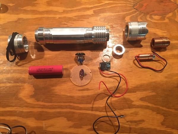
I started with these parts:
-3.5W NDB7A75
-S4x bare aluminum host
-1 LG he2 li-ion battery
-SXB boost driver set to 3.2A on test load with four diodes selected. w/4.5A max
-1 momentary side switch. Rated at 3A @ 230VAC
-drilled out pill
-3 element lense
Ready set go!


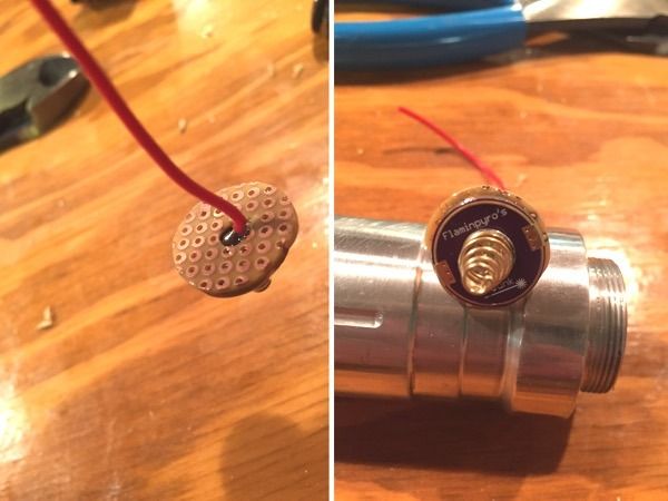
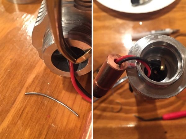
The first thing I did was modify a contact spring I purchased from Flaminpyro, it doesn't quite fit so I had to add a pcb board to the back and re solder the heavier awg 26.


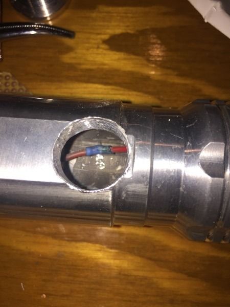
Next I had to drill a 5/8th hole. To leave room for switch I decided to use an SXB boost.
This was tricky... I had a 1/2in bit. After that I used a burr bit. My instinct told me that I should protect the wire inside. Ignoring that I proceeded... The bit burst through and nailed the wire. It was trimmed back and spliced well with solder. :/ live and learn.
It looks dirty in the photo but is pretty solid.


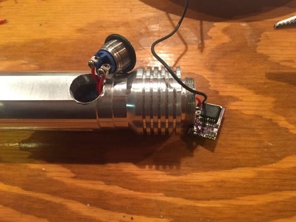
The switch was installed and the driver setup. (The driver was set to 3.2A before this I just installed it at this point)


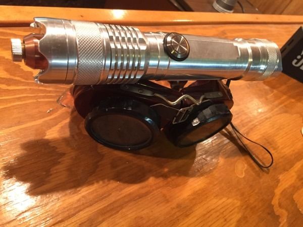
Originally I designed this for the pill to thread into host then crush the brass ring between the pill and body but the ring was too small. Ordinarily the contact point would be here for a buck drive but this isn't standard. Ahh, I had to improvise:

The laser head threaded perfectly on the host body and pinched. Hardly noticeable.


Thread the bezel ring on with the extented copper heat sink and everything should work well. Right? Mostly


Beam shot!


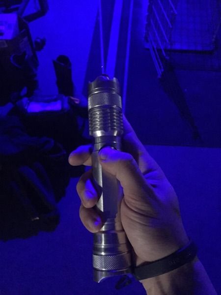
Here's where things get interesting. I'm happy with this build just need to iron out some details.
The beam didn't appear to be 4W bright. I have seen this diode in action and I'm not getting the expected power.
When I metered the laser I got 2274mW. o_O

I qurered Jordan about the diode and he suspected the current draw on the SXB was too great.
I have 1-1.2ohms of resistance in each switch(tail and side) and the resistance in the wiring fluctuates between .9 and 1.1.
The current draw on the tail cap is measured at 2.57A with the DMM.
I switched the battery to a Panasonic. No change.
Options? Switch to a buck and use two 18350s ?
Unfortunately I don't have a variable DC power supply but I could bypass the switches and connect directly to the driver to see if that is where the problem lays.
Thoughts, comments, advice?

Thanks for reading everyone!
I know it's been awhile since I have posted a new addition to my collection.
:thanks:
 
Last edited:


Joined
Feb 25, 2010
Messages
1,643
Points
113
DWH....Great build thread !!! All who share their build up's and down's really should get much credit for shining a light....for others to follow !!!

From those who are about to build (again)...we salute you !!! hahaha

I truly prefer a side switch !!! Seems lika No Brainer as far as ergonomics are concerned !! One hand to I/O !!! Yes....vs.....holding the unit up....lika spear....up in the air for " thumb I/O" Go figure.....but then....the butt end switch is tried and true....and more compact.....just cannot have it all hey ???

Now....your problem !!! First.....make sure the LD is not the root cause !!! Get a bench top PS......and eliminate that as the culprit....them.....as you propose....isolate/eliminate to pinpoint the problem !! Lotsa help....right....just throw more $$$ at it !!! hahaha
Sure....you got plenty extra this time of the year !!!

Thanx for sharing !!! Beam Out !
 
Joined
Aug 16, 2013
Messages
971
Points
43
Roger that on the ergonomics. I like side switches but they always tent to make things tougher.
I really do need a 30V 10A power supply. If you know anyone who is selling one let me know. Those cheapos on eBay are always an option but I haven't used one before to know if they are reliable enough.
Thanks!
 

Garoq

0
Joined
Aug 27, 2010
Messages
1,525
Points
83
Great mod to the host and thanks for sharing! Plenty of room for that side switch. Could it be that the SXD needs more heatsinking?
 
Joined
Aug 16, 2013
Messages
971
Points
43
Updated. I by passed both switches and all internal wiring. Battery directly to the drive whoosh. 3.8W very quickly. Ok crossed the driver as a variable off that list. That seems to be working fine. Nowww to dive back into the wiring and switches to find out where the chock point it.

-----—---------
Mission switch extraction unsuccessful. It's a garbled mess with some damage. To the body. Maybe I went heavy on the super glue.

Using a magnifying glass I can read the fine print on the switch. 3a@ at 12volts. Upon further investigation the seller on eBay had received other negative feedback for advertising a 30amp switch and it only being 3. The search for a better switch continues.
 
Last edited:
Joined
Jul 10, 2015
Messages
9,892
Points
113
I'm sure you know you will need a top notch INR or IMR battery to run a 7A75 off a boost drive via single cell.

I have been testing batteries under load and I use big heatsinks and burn for 5 minutes at a time, the longer you are on the more the battery matters.

Also your wiring and switch create resistance, larger wire kept as short as possible and a low ohm switch are even more important with a single cell boost driving a big diode.

Good luck, it looks like it will be a nice build.

Here's a quick battery test, the lesser batteries will fall faster the longer you run as well.

If that sanyo? your using is not fresh, fully charged, and IMR/INR or better then that and a little extra resistance will likley be your culprit.

Oh, I have had a run of bad spring boards lately, both were older zeros I think, but they both went dead short, maybe I got them too hot soldering on the spring, but 1 shorted out mid use.
I do better when I make my own and when I load test my own they carry a lot of current, you may want to test your spring board too.

Not the best video but you can see how your boost driver in order to supply the diode with 5 volts at 4 amps will have to drop to less than 1 ohm, so a low resistance circuit and a very good battery will be needed. p.s. I don't smoke but I've been burning wood like a maniac so I'm losing my voice a bit.
 
Last edited:
Joined
Aug 16, 2013
Messages
971
Points
43
Hey thanks for your comments, right now I am using 2 batteries For testing this build. LG he2 & the NCRb. The host isn't designed to accept a 26650 tho it could be machined to accept one.

While thinking about this I have concluded one critical error I made was not testing the side switch under a load. The lead length could be an issue too. Hmm
 
Last edited:

Pman

0
Joined
Nov 28, 2012
Messages
4,447
Points
113
I have run into a LOT of switch problems as you described lately. You should basically have 0 resistance across it and you get a reading like you mentioned instead. Luckily I had a few extra switches and was able to change them out after testing and see that they had 0 resistance.
However, I've also run into some anodizing issues where the connections between sections of the host were not good. I take a metal dremel brush (not the brass ones but the silver ones) and go over all the surfaces especially including the threads and the end pieces and where those ends will touch the other piece of host until every section reads no resistance. It's always best to do this before starting you rebuild as it's easier than taking everything apart again.
Because most drivers can work well in a range of voltages lately I've found that the extra battery voltage can overcome the switch issue way more than the host issues. This problem most recently cropped up in the cheap 501b hosts that some are selling. The last 2 I got both read about 1 ohm across the switch but the bigger issue was the anodizing.
 
Joined
Aug 16, 2013
Messages
971
Points
43
I have run into a LOT of switch problems as you described lately. You should basically have 0 resistance across it and you get a reading like you mentioned instead. Luckily I had a few extra switches and was able to change them out after testing and see that they had 0 resistance.
Do you know where a reliable source for high amperage momentarily switches? The eBay seller I bought it off claimed it was rated for 30amps but that was wrong. My local electronics store I used to buy this stuff from is out of business.

Red cowboy seemed to have a good collection. Maybe he will part with a low resistance switch. Cough* cough*

I've received a couple of suggestions for a 26650 version of this host and it is definitely a possibility for the future.
There is always the possibility of selling a tube spacer.
The demand for larger hosts for more powerful diodes must also demand larger current draws and capacities.
In my opinion it is a good avenue to explore.
 
Joined
Jul 10, 2015
Messages
9,892
Points
113
That switch you have looks like it's aftermarket automotive, it really should be ok.
I really think 1 battery is just not enough for the 7A75, 5 volts at 4 amps into the diode, you need more into the driver.


I know you said you got 3.8W out with the battery straight into the boost and it's a LG he2 ? was it at full charge, if you run it heat sinked for 30 seconds what's your output with the battery going straight into the driver?

You can try a switch with beefy contacts and the biggest wire you can fit, but 1 battery may not be enough for a 60 second duty cycle.

The right way to measure a switch for resistance is to run a current through it and measure the millivolt drop across it while powering a load.

Your meter needs to have a relative zero for your leeds to be exact. A cheap meter without a relative zero function can read .5 ohms from it's own probe leads, you can't go by that.


I will be glad to send you some switches, but you may need more battery.

I zeroed my leads with this microprocessor meter and these 16 amp at 12 volt rated switches meter 0.04 - 0.02 ohms, and 0.00 -0.01 after exercising half a dozen times as they are new.

The far right pole is for the little led in the switch, you can just cut it off or connect to ground and the led will light when the switch is on, up to 12 volts, they do light on 3.7 too just not as bright. + to battery, A to driver positive, Ground is ground for the switch illumination when it's on.
If you want to switch ground then the led switch light won't light as it's a led.

I will be glad to send you a few of both, just pm me your addy.
SANY0383_zpskijzgzy2.jpg

SANY0378_zps0cjj9cn3.jpg


These momentary contacts meter 0.15 if you press lightly, but if you press firmly they meter 0.07 they are rated 3 amps at 250 volts but they will probably work fine for you and they will fit, I will send you some of each.

Also I noticed while testing these that after exercising them half a dozen times the resistance dropped to 0.05 - 0.00, they are new so a little wear in is expected with less than industrial switches.
SANY0384_zpsmykhty48.jpg


I exercised these and they are coming up near zero ohms, the 3amp 250 volt momentary buttons will carry your load just fine I would think, you can test them table top before assembly, I would not hesitate to use them if they fit, but the square butt switches are sturdy, I use 1 on my 07E.
SANY0391_zpsx6vskgjq.jpg

Free to a good home :beer:
 
Last edited:
Joined
Aug 16, 2013
Messages
971
Points
43
Hmm let me do some more trouble shooting. The original switch did not Survive the extraction so it was scraped the hole drilled is 5/8ths.
I have one 26650 on hand. I could wire this battery to the host as it was to test-
- the host body,
-Positive contact pad
-Rear tail switch.

Duty cycle will have to wait for now.

The problem is I would have to add more wiring (could use 14awg since it won't be part of the finished build) and my Klein DMM might have resistance in the banana clips.
Red cowboy, I appreciate the offer if you are willing to send me some switches pm me your pay pal account and I will at least pay the shipping.
 
Last edited:


Top