Welcome to Laser Pointer Forums - discuss green laser pointers, blue laser pointers, and all types of lasers

Buy Site Supporter Role (remove some ads) | LPF Donations

Links below open in new window

FrozenGate by Avery

Switching Driver for 445nm / 405nm


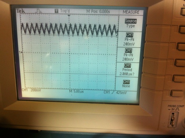
The site is back up. I have put it on a scope and do not understand what I am seeing.

I'll post everything. Only thing that I haven't done yet ismthemsoft start, I will add that after I make the initial post. I've never seen a waveform like this. I looks,jacked to me. My voltmeter just chews it up and spits out nice numbers on the test load, but the scope is not pretty.

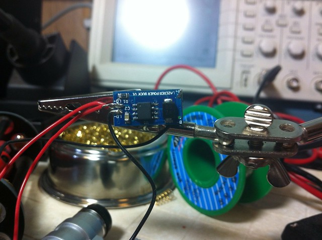
Here is a shot of the driver...


Untitled by tsteele93, on Flickr

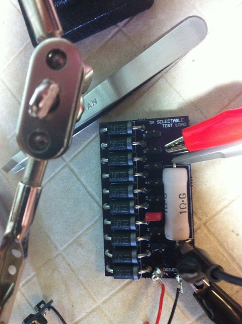
Hooked to the test load at a four diode setting...


Untitled by tsteele93, on Flickr

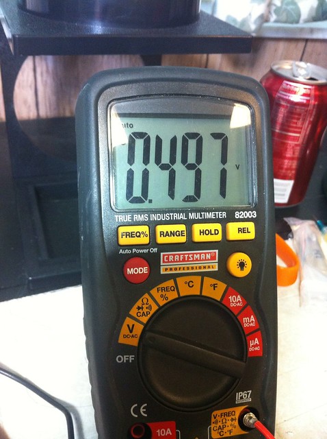
497mV = 497mA on the Jufran test load.


Untitled by tsteele93, on Flickr

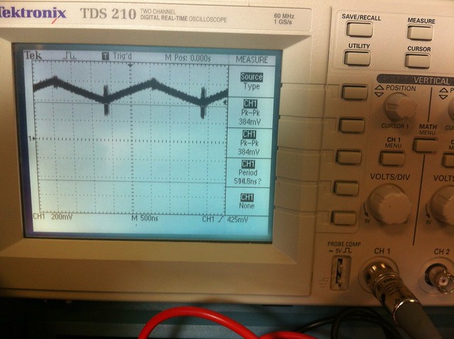
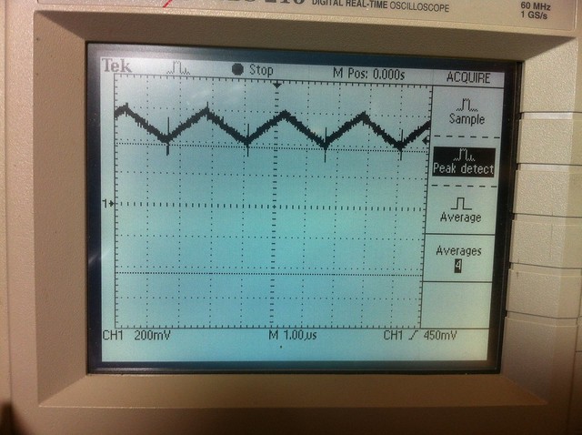
And scope shots...


Untitled by tsteele93, on Flickr


Untitled by tsteele93, on Flickr

Any thoughts?

I'm not hooking this up to a $70 12x 405 diode!
 
Here is shot on AUTOSET - I can't get the soft start without doing a video. Probably need to change the trigger level. Basically it looks just like this pattern, except it starts around zero and the whole waveform gradually goes higher until it reaches ~499mV average.

It just rises over about 2 seconds... Anyway, here is the AUTOSET pic...


Auto set by tsteele93, on Flickr
 
Ooph. That looks pretty bad - really nasty triangle oscillations between about 390mA and 610mA. Wouldn't hook that up to an expensive diode, either.
 
Well crap any idea why these scoped so badly? could it be component arrangement or just a slap fail in design?

thank you Mr. Steele for scoping these.
 
Last edited:
I have no idea why they look like that. I'm going to try to put some caps on it and see if that smooths it out.

I'll also try to scope it under different scope settings.
 
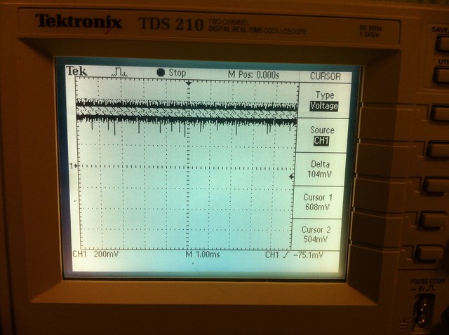
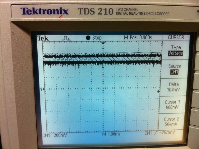
Here are a couple of runs at 1ms rather than 1us, which is not as good - but does show the spikes.

The first one is as shipped.


Untitled by tsteele93, on Flickr

The rest of these scans are after I added (stacked - parallel) 2.2uF capacitors to the caps on the board to see if it would smooth things - which it did not seem to do ...


Untitled by tsteele93, on Flickr

Here are some with better time resolutions...

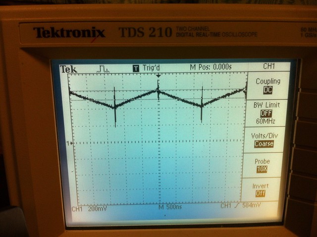
This is 500ns - DC coupling


Untitled by tsteele93, on Flickr

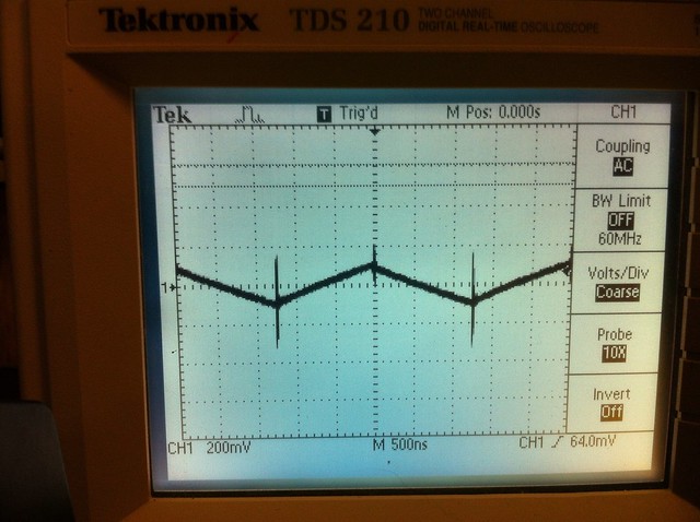
This is 500ns - AC coupling for foulmist. I don't see any difference except you lose the DC info of the driver's output current.


Untitled by tsteele93, on Flickr

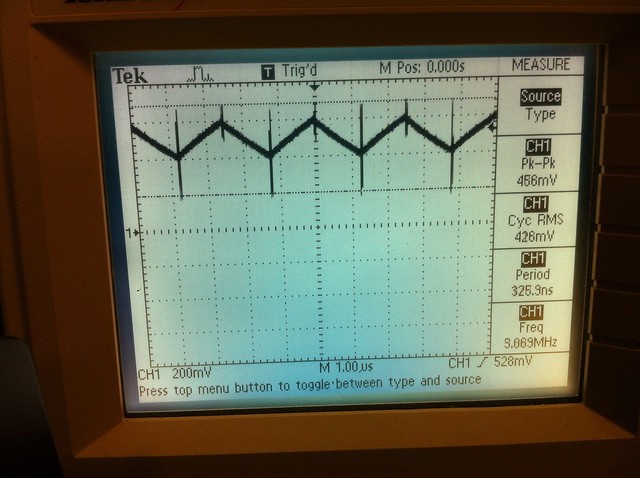
Here is a DC shot at 1uS


Untitled by tsteele93, on Flickr

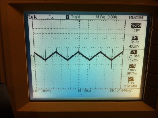
And here is the AC shot with 1uS


Untitled by tsteele93, on Flickr

Maybe someone more knowledgeable than me can comment, but I would be afraid to put this on a diode unless it was very robust. I think it looks terrible. But I am no expert so maybe someone else can comment.
 
Last edited:
I think it's pretty bad. The ripple is from 200ma to 700ma (half an amp!). That's some big ripple.
 
I'm new and using this driver , it goes dim after I switching on for like 10-15sec .. >.< any idea?
 
Maybe , never know this driver need heat sink ..
but not so fast going dim ;(
the metal piece at the back of the regulator probably is the heat sink for it ?


Back
Top