Welcome to Laser Pointer Forums - discuss green laser pointers, blue laser pointers, and all types of lasers

LPF Donation via Stripe | LPF Donation - Other Methods

Links below open in new window

ArcticMyst Security by Avery

Soldering thread

WizardG

0
LPF Site Supporter
Joined
May 9, 2011
Messages
1,170
Points
113
One tiny nit to pick here. If we're talking about Pb/Sn solder, 60/40 solder is not eutectic solder, that would be 63/37 Pb/Sn.

What kind(s) of lead free have you tried? SAC305 is pretty user friendly.


Benm

0
Joined
Aug 16, 2007
Messages
7,896
Points
113
You are correct on that.

I didn't want to overcomplicate things, and since it's usually labeled 60/40 i stuck with that.

Actual solder formulations differ from the eutectic tin/lead mixture a little bit. Obviously a part of the weight is actually flux, not solder, but some solders also contain a small amount of copper. This helps to prevent component leads actually dissolving in the solder, potentially weaking the leads.

Another reason for having slightly less tin than eutectic is that things like component leads and even PCB pads are ofted tin-coated, not lead/tin-coated to begin with. Having a bit of excess lead in the solder can help ensuring the final joint actually is closer to eutectic, though it's not that critical really.

I've used solders containing some silver as well for RF work: things like inductors are actually made of silver-plated copper to get the lowest possible loss (due to skin effect) there, and 'ordinary' solder dissolves that silver away from the joint.

These are all pretty specific things though, the stuff you want for hand soldering is something marked 60/40 with rosin flux cores. If they mark it 63/37 that's also fine, but recently i've seen the vast majority labeled 60/40.
 
Joined
Jul 4, 2008
Messages
2,499
Points
113
One tiny nit to pick here. If we're talking about Pb/Sn solder, 60/40 solder is not eutectic solder, that would be 63/37 Pb/Sn.

What kind(s) of lead free have you tried? SAC305 is pretty user friendly.

Correct, and I mistyped this. I checked the spool that I have at home and sure enough it is indeed 63:37. When I purchased this I was told it was 60:40 with a label of Eutectic which is erroneous. It starts to melt at 360F but really becomes easier to work with at around 400-410F I find with the Hakko. :thanks:

Eutectic is the best to use hands down. Cheap, plus reasonably lower temperature to work with.

I have used SAC305 for the soldering course last year. It's a pretty popular choice for Pb free boards.
It is however a high temperature solder and used around 265° -270°C (509° -518°F) which would not be a fit for our LD pins
when soldering to them. The lower temperature the soldering we can expose to the LD pins to the better.
Even better would be InSn but good luck getting some of that.
 
Last edited:
Joined
Sep 12, 2007
Messages
9,399
Points
113
Funfact (nitpicking²): metallurgically, Eutectic mixture is precisely 61.9% tin. The extra tin in the 63/37 is to account for some of it oxidizing during the soldering process.
 
  • Like
Reactions: GSS
Joined
Jul 4, 2008
Messages
2,499
Points
113
Funfact (nitpicking²): metallurgically, Eutectic mixture is precisely 61.9% tin. The extra tin in the 63/37 is to account for some of it oxidizing during the soldering process.


How it's done in the Animal kingdom. :na:
nitpick.jpg
 
Joined
Oct 11, 2016
Messages
807
Points
43
I damaged my adjustable weller so now I just use the cheap $4 harbor freight tools irons because when the tip wears down I just buy another iron. I keep a few handy. They're 40w. Does what I need.
 
  • Like
Reactions: GSS

Gabe

0
Joined
Jan 10, 2015
Messages
1,147
Points
83
Real beginner to soldering here too... All I have is a wood burning iron, no temp control or anything. Ain't pretty, but the job gets done. Sometimes I have problems with the solder's surface tension, too low and it makes spikes when I pull the iron away, or it will stay as a bead on the side of the tip and be a hassle. It can be useful, though, for making little solder bridges in place of tiny wires. My first real intro to soldering was making a light panel out of LED strips for macro photography... I'll post pics in a bit so you can make fun of the soldering work. :D
 
Joined
Jul 4, 2008
Messages
2,499
Points
113
Real beginner to soldering here too... All I have is a wood burning iron, no temp control or anything. Ain't pretty, but the job gets done. Sometimes I have problems with the solder's surface tension, too low and it makes spikes when I pull the iron away, or it will stay as a bead on the side of the tip and be a hassle. It can be useful, though, for making little solder bridges in place of tiny wires. My first real intro to soldering was making a light panel out of LED strips for macro photography... I'll post pics in a bit so you can make fun of the soldering work. :D

Yup, you'll need a decent soldering iron to do any work with electronics. ( cheap ones by hakko or weller work fine but they'll be good to a certain temp range and no more or less) try and get one that works with 60/40 and 63/47 and you'll be good to go.
The spiking you speak of is also referred to as solder flagging.
There can be several reasons for this
a) A component that has a high mass may have a lead of the same size as other parts. During pre-heat of the board there may not be an opportunity for heat to be absorbed by the lead to overcome this thermal load. As the leads of the component separate from the wave they will cool much more quickly, leaving either spikes or shorts.
b) Another reason can be due to improper fluxing/ inconsistent fluxing
c) In a worst case scenario it can be caused by mixing Pb free solders with PbSn alloys.

You should always use the solder intended for a given board type.
Never mix solders up or you'll be asking for problems.


I've been through several irons now. 4 while in S.Korea, and 1 here in Canada.
I think the digital Hakko was an excellent move.


Last edited:

Benm

0
Joined
Aug 16, 2007
Messages
7,896
Points
113
You should always use the solder intended for a given board type.
Never mix solders up or you'll be asking for problems.

Not really. There is no 'board type' specific for a type of solder. The base material of the pcb is usually copper, just plated with some type of solder. Often lead-free for industrially produced units.

But this is not a permanent thing. If you replace a component on a lead-free board you can still use lead based solder perfectly well. The best approach is to flow some lead based solder onto the exiting pads, let it mix with the lead-free stuff and then remove it (using a suction system, litze, or just whacking the board on its edge as you prefer).

After doing that, lead based solder will flow perfectly well onto the now mostly clean pads and component leads to be connected.

In most cases you can visually tell if a solder joint is good: it should be shinly all over the surface, and have a shape like the solder just wicked into place.

Some factory soldered cheap electronics lack these qualities, and you should be careful when using them. Lead free solder can also make joints that look good, provided that the manufacturer used the proper temperature profile and all.

Bodges done by hand with lead free solder usually are crap, and if they involve bodge wires you can often just rip them off the board - something almost impossible to do with a well soldered copper wire onto a board... in which case you'll break the wire or rip the trace off the board, but not break the solder bond.
 
Joined
Jul 4, 2008
Messages
2,499
Points
113
Not really. There is no 'board type' specific for a type of solder. The base material of the pcb is usually copper, just plated with some type of solder. Often lead-free for industrially produced units.

But this is not a permanent thing. If you replace a component on a lead-free board you can still use lead based solder perfectly well. The best approach is to flow some lead based solder onto the exiting pads, let it mix with the lead-free stuff and then remove it (using a suction system, litze, or just whacking the board on its edge as you prefer).

After doing that, lead based solder will flow perfectly well onto the now mostly clean pads and component leads to be connected.

In most cases you can visually tell if a solder joint is good: it should be shinly all over the surface, and have a shape like the solder just wicked into place.

Some factory soldered cheap electronics lack these qualities, and you should be careful when using them. Lead free solder can also make joints that look good, provided that the manufacturer used the proper temperature profile and all.

Bodges done by hand with lead free solder usually are crap, and if they involve bodge wires you can often just rip them off the board - something almost impossible to do with a well soldered copper wire onto a board... in which case you'll break the wire or rip the trace off the board, but not break the solder bond.

During our electronics classes we discussed improper soldering. While you're right about the use of SnPb solder on lead free boards being fine for repair or when the board part has not yet been propagated., it's not ok (against RoHS) to use it on already "tinned" areas or on Pb Free components. Discussed in the class was the potential for fragility/ breaking caused by
the mixing of alloys. Our instructor was ex-military and this probably had something to do with his opinion.

Removing whatever Pb free solder on the board before soldering with leaded stuff is always best practice as you've suggested. :tinfoil: :thanks:


@ Cyparagon
I've been "asking for problems" for years now. Where are these problems you're promising me?

Not promising problems. "In certain circumstances when Pb free solder is able to mix there appears to be a firm contact on the board when
in fact a cold solder joint has been made." This I am quoting directly from our Prof. Therefore best practise is not to mix the alloys up.
I am not saying you physically can't repair a board with Pb solder, just that if it has the lead free solder in then your best bet is to remove it then repair with the lead.

We have conducted some initial testing on mixing RoHS compatible components and lead components on the same PCB, but only with manual soldering using lead solder. No report or final conclusions have been made, but our initial findings is that this causes a lot of poor solder joints (cold solder) that looks like proper solder joints (proper wetted).
Martin Sollien, KDA, Norway (defense industries)

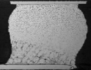
Just a pic showing a mixed solder ball. Looking at the bottom you can get a sense of the crystallization below. The bottom of the solder ball is the area in which the Pb is separating out from the mixture created with the Sn:Ag:Cu:Sb ..etc (fairly typical lead free solder alloys).
mixed_sb.jpg


So if you are stuck with this mixed technology, to minimixe risk see about optimizing your process at a high enough temperature so that the SAC BGA balls melt. However, clearly it is best to avoid "mixing" lead-free and tin-lead alloys in the first place. Cheers, Dr. Ron - See more at: http://www.indium.com/blog/mixed-le...hnical-topic-at-apex.php#sthash.oCpJk11Y.dpuf
 
Last edited:

Benm

0
Joined
Aug 16, 2007
Messages
7,896
Points
113
lead free boards being fine for repair or when the board part has not yet been propagated., it's not ok (against RoHS) to use it on already "tinned" areas or on Pb Free components. Discussed in the class was the potential for fragility/ breaking caused by
the mixing of alloys. Our instructor was ex-military and this probably had something to do with his opinion.

It also depends on what you mean by 'tinned': It can have two meanings here: Commonly you refer to a lead/pad/etc as 'tinned' when wetted with solder (regardless if it contains lead or not), but it can also mean 'covered by tin', as in tin-plated by chemical or electrochemical application of pure tin metal onto another metal (like copper).

If it is actually just tin plated, like many component leads are, using lead based solder poses no problem. If it actually means tinned as-in covered by lead-free solder, using a lead based solder could create problems like that awful join in the picture.

On the other hand: If in doubt, use lead based. Trying to fix lead-free joints with leaded solder is FAR easier than doing things the other way around (it's borderline impossible to get a good solid joint between things that were once connected by lead based solder using lead free unless you scrape them clean to bare metal first).
 
Joined
Jul 4, 2008
Messages
2,499
Points
113
It also depends on what you mean by 'tinned': It can have two meanings here: Commonly you refer to a lead/pad/etc as 'tinned' when wetted with solder (regardless if it contains lead or not), but it can also mean 'covered by tin', as in tin-plated by chemical or electrochemical application of pure tin metal onto another metal (like copper).

If it is actually just tin plated, like many component leads are, using lead based solder poses no problem. If it actually means tinned as-in covered by lead-free solder, using a lead based solder could create problems like that awful join in the picture.

On the other hand: If in doubt, use lead based. Trying to fix lead-free joints with leaded solder is FAR easier than doing things the other way around (it's borderline impossible to get a good solid joint between things that were once connected by lead based solder using lead free unless you scrape them clean to bare metal first).

You are absolutely correct. I typed this at 5am.. .so I was talking about the middle scenario when you've already got Pb free on the board.
That bead cross section is exactly the scenario defense and aerospace companies dredd, so much so that lead free is completely banned from being used in their facilities.
(They are not bound by RoHS rules)

Lead free solder has come leaps and bounds over the years but it is quite unreliable in environments with high shock or extreme temperature swings. NASA also uses Sn63:pb37 as well.


I agree with the last bit :beer: Also the heat at which Pb free melts is also very hard on tips which will oxidize readily.

On the other hand: If in doubt, use lead based. Trying to fix lead-free joints with leaded solder is FAR easier than doing things the other way around (it's borderline impossible to get a good solid joint between things that were once connected by lead based solder using lead free unless you scrape them clean to bare metal first)

Yup.. couldn't agree more. :beer:
 
Last edited:
Joined
Jul 4, 2008
Messages
2,499
Points
113
SMC soldering using a DIY solder paste dispenser

Here's an interesting video showcasing SMC solder paste and SMC reflow


DM dispenser, for solder pastes and adhesives


DIY SMC reflow oven


Benm

0
Joined
Aug 16, 2007
Messages
7,896
Points
113
You can do reflow work with lead-free solder using fairly crude things like such an oven.

The important part is that the pieces are mechanically fixed to eachother during the cooling of the solder, which would be the case for components glued to a board like that.

I've also seen videos of people soldering such fine pitched components by hand using lead based solder though. Personally i don't think i could do it right now, but it would be possible to learn - as long as there is a good solder mask on the board.

One thing leaded solder has going for it is very strong surface tension, making it easy to reflow components even if you melt all of their pins at one (like with smd resistors). The surface tension of the solder just pulls the component into place if it's not glued down.

If you look at cheaply produced stuff with leadfree solder you can sometimes see that all components are just offset from the optimum position. This happens when pick and place machines are slighly mis-aligned. Glued-down wave soldering cannot do anything to correct this. If you did the same work with components that were not glued down and reflow-soldered with lead based solder the surface tension is strong enough to straighten them out on the board.
 
Joined
Jul 4, 2008
Messages
2,499
Points
113
You can do reflow work with lead-free solder using fairly crude things like such an oven.

The important part is that the pieces are mechanically fixed to eachother during the cooling of the solder, which would be the case for components glued to a board like that.

I've also seen videos of people soldering such fine pitched components by hand using lead based solder though. Personally i don't think i could do it right now, but it would be possible to learn - as long as there is a good solder mask on the board.

One thing leaded solder has going for it is very strong surface tension, making it easy to reflow components even if you melt all of their pins at one (like with smd resistors). The surface tension of the solder just pulls the component into place if it's not glued down.

If you look at cheaply produced stuff with leadfree solder you can sometimes see that all components are just offset from the optimum position. This happens when pick and place machines are slighly mis-aligned. Glued-down wave soldering cannot do anything to correct this. If you did the same work with components that were not glued down and reflow-soldered with lead based solder the surface tension is strong enough to straighten them out on the board.

at some point I am going to have to show off my SMC board that I completed without an oven. It was using solder paste and a hot air (rework) soldering gun. I also completed one with only a fine needle tip with a Hakko FX951-66 soldering station. It was a skill test to see how precise we could solder using only our hands + pair of helping hands grips.

Pics will be along sometime shortly.
As you can tell I love soldering I feel like it is a form of meditation . :p

Below is an interesting video link to Pb free solder paste developed by Indium corporation. It is referred to as SACm which is ~97.5-98.5% Sn, 0.5-1.0% Ag, and 0.5-1.0% Cu, with dopant levels of Mn.
The overall result is a solder paste that is very similar to SnPb eutectic.
I find this very fascinating.

http://www.indium.com/solder-paste-and-powders/SACm/video/SACm-Video.mp4
 
Last edited:


Top