Welcome to Laser Pointer Forums - discuss green laser pointers, blue laser pointers, and all types of lasers

LPF Donation via Stripe | LPF Donation - Other Methods

Links below open in new window

ArcticMyst Security by Avery

Remove shunts from MOT: Drill out, or punch out?

Joined
Jan 14, 2009
Messages
1,452
Points
83
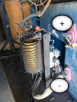
Bigger one on the left in second picture is probably an inductor as its two windings , one on each leg in series .


Though I cant tell from the picture but it looks like it dose have a smaller winding so it could be a saturable reactor for current control .
 
Last edited:


Joined
Jul 4, 2008
Messages
2,499
Points
113
Hey folks, Im bit perplexed by this transformer configuration though I believe it's basic.
I pulled it from a very old miller welding machine and plan to use it as a ballast for a 10kvA pole pig. The core(s) seem to be large enough(100kg easy) where saturation will be less of an issue. It appears as though there are two independent transformers here or is one a primary and the other a secondary which I'm inclined to believe. I'm very far away from build the TC but this might be a good option for a inductive ballast whether I winding my own primary or use what's there short the secondaries in series. Can anyone point me in the right direction where I can learn more about transformers just like this?
I can tell from the name plate it steps down to 32V and the smaller coil has various taps for voltage input from the red bus bar.


Though I can't tell from the picture but it looks like it dose have a smaller winding so it could be a saturable reactor for current control

Yup, that's exactly what I was thinking too. :thanks:
 
Joined
Aug 16, 2013
Messages
971
Points
43
Today I'll be back in the shop to take a look at the rest gutted welding machine. Those visible leads were connected to a plethora of switch options from high range, low range, reverse polarity, even an ac-D.C. Options. No big smoothing capacitors but trust me guys there's olddddd technology in this machine I've never seen before. :wtf:

Upon further investigation I completed agree there's a saturable reactor in this photo because the Main current is adjustable by a very small pot on the front panel on the machine. Not large crank handles that I've seen before.

However on the taller transformer I don't see any wires around the core that might be used as a DC Supply. Where I do see these wires are around the smaller transformer core. (See attachment)
I also power the XMER up with 120vac and measured 46vac across the outputs.
I connected the other core in series and measured the output and it's the same.. I think it might be time for a load test!
 

Attachments

  • IMG_2820.JPG
    IMG_2820.JPG
    109.6 KB · Views: 20
  • IMG_2823.JPG
    IMG_2823.JPG
    109.8 KB · Views: 20
Last edited:


Top