Welcome to Laser Pointer Forums - discuss green laser pointers, blue laser pointers, and all types of lasers

Buy Site Supporter Role (remove some ads) | LPF Donations

Links below open in new window

FrozenGate by Avery

Remove shunts from MOT: Drill out, or punch out?

The old Sanyo radar range XMFRs are very heavy and massively overbuilt. this is good. It means they can be run above spec (~ +50%) without having much in the way of issues. The smaller XMFRs aren't very durable.

Benm is also quite correct here as well. So I'll second his opinion as well. :beer:
I'd also like to add that the large transformers will start smoking long after your house wiring starts burning.
This is why I explained about the shunts actually not being very helpful in controlling current draw,
but a single (radar range) mot without a secondary cap will draw about 35-40A at 120Vac.
This is also why the 2000VAC rated cap in the secondary is required.

Those linked videos were intense. Hell of an arc. I don't think Best Buy's geek squad would take that mother board back.
-I actually do have an array of 240v incandescent light bulbs I was using to bleed down capacitors benm, so that's not a bad idea.
Can you expand upon this "radar range" transformer? Is this a special application XMFR or Class.

Scenario: I have a large MOT. Input is for the north American voltage of 120VAC. I have at my disposal a 240v 30A outlet with a 7.8kVA variac. It's it possible to over drive the mot that 50%?
Correct me if I am wrong but the difference between a microwave for the United States vs one from Australia the number of turns on the primary?
What would happen if I ramped that F****R up to 240Vac? Let's assume the core was ground. Would the insulation break down between the windings and core?
This is all precursor research for possibly building a large large RGTC in the future.

Australian outlets use 240V 50Hz, the winding turns on the MOT primary are approximately half of what would be needed to run the 120V version. (somebody correct me if I have this reverse) The turn ration between primary to secondary is key here. On the N/A version the ratio between turns is approx. 20:1, on the 240Vac version (UK, S.Korea, Australia and about 80% of the world) what you have is essentially a 10:1 ratio XMFR.
Going back to the overdrive thing... DO NOT EVER run any microwave transformers past their voltage rating. The larger radar range XMFRs cores seem to saturate at around ~160Vac... afterwhich they will become large red-hot electromagnets after their core saturates.

What you CAN do is run these larger transformers well past their current ratings. 50% more in fact after you punch their shunts out.
These transformers run better without the dammed shunts, they'll require ballasting either inductive, or secondary (Capacitive).
It is very easy to be able to pull 2-3A @2.2-2.5Kvac from one of the large Sanyo branded transformers.
 
Roger that not exceeding the voltage ratings.

I have a few extra mots and caps at home I can experiment with at the end of the month.
I'd like to build a robust inductive balast. hvtesla.com has great information on the subject but core material might be hard to come by.

Ps where did you salvage all your caps and mots back in the day?
 
I'd also like to add that the large transformers will start smoking long after your house wiring starts burning.

That would depend on where you live, and how many transformers you are trying to use.

In europe most outlets are 230v/16a, and you can run two 1.5 kW-input power mircowave ovens at full power from one outlet forever. Something similar would apply to australia.

The wiring in houses with breakers at 16a usually is 2.5mm2 solid core copper, which can safely handle double that current if installed properly according to code (following how many wires you can put in a tube of certain diameter etc).

Breakers are also designed to deal with this: On a typical domestic 16 amp outlet you can draw 32 amps for about a minute before the breaker trips. It will trip instantly at a current of over 80 amps (5x the rated current of the system) on the vast majority of domestic systems.

These specs go pretty far: even a light circuit needs to be wired with 10 amp capable 1.5 mm2 wire. Even if there are several light points connected to one switch, the idea of installing 2300 watts of lights on any installation called 'ordinary' is over the top.

Then gain, we do get very few electrical failure fires in the wiring here: by the time your appliance is actually on fire you might worry about the wiring in the walls, but if the breakers are okay with it you could just melt microwave oven transformers to your desire without any risk to installed wiring at all :D
 
Roger that not exceeding the voltage ratings.

I have a few extra mots and caps at home I can experiment with at the end of the month.
I'd like to build a robust inductive balast. hvtesla.com has great information on the subject but core material might be hard to come by.

Ps where did you salvage all your caps and mots back in the day?

Answer: Free junk yard Microwave ovens and parts stores. We got everything for free. :eg:

Nobody wanted to keep those radar range oven transformers as they were far too heavy and seldom used. Expensive to recycle...YadaYada..

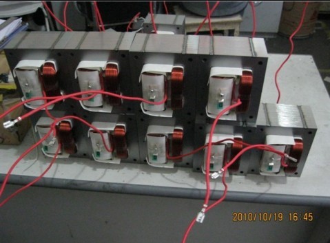
measurements on these are approximately ~9"W x 10"H.
They were used primarily in industrial microwaves and older microwave ovens from the 1980s. Sanyo and Mitsubishi-denki were primarily the producers of those transformers.

Here is a picture of a stack of these on a bench. Remember how large each of these are/ ~7.5-8Kg or so each if memory serves me correctly.
201384185250393.jpg
 
Last edited:
That would depend on where you live, and how many transformers you are trying to use.

In europe most outlets are 230v/16a, and you can run two 1.5 kW-input power mircowave ovens at full power from one outlet forever. Something similar would apply to australia.

The wiring in houses with breakers at 16a usually is 2.5mm2 solid core copper, which can safely handle double that current if installed properly according to code (following how many wires you can put in a tube of certain diameter etc).

Lucky I'm in the UK : P . We usually have two or three rings in 2.5mm2 backed by 32A Breakers , Downstairs , upstairs , kitchen .

7.5Kw to Pull per ring , With the most I've pulled being 7Kw
 
Last edited:
The UK is pretty amazing when it comes to its mains power systems really. Running at 240 volts also helps a bit compared to mainland europe being stuck anywhere from 220 to 230 (up here on the 15th floor that is 215-225 at best).

One downside of the uk system are the power plugs: they are just so enormous, not to mention their wide application in hell where sinners are to walk over upturned ones on a daily basis.

I think one of the chief benefits of mainland european plugs is that you do not need to have an earth pin to unlock the socket. This way we can have the thin and light 'euro plugs' as well as the heavy-duty, grounded, 'schuko' plugs for things that actually need a lot of current.

As for current handling of installed wires: 2.5 mm2 is considered only good enough up to 16 amps here, unless you use a fast breaker allowing 20 amps. This is over-dimensioned indeed, most domestic power systems could handle 32 amps continously, i guess it's just a safety factor built in for the most extreme conditions (very hot weather, clumsy-but-just-to-code installation and such).
 
The capacitors in the shown schematic are not a ballast, they are for achieving 50Hz/60Hz resonance for producing big arcs.


Sooner or later the insulation will break down if you put 4 transformers in series. normally they are earthed on the inner side of the high voltage windings at the core, and if you cut that connection to the core, the windings will float on high potential against earth. Then the insulation will break down and internal arcing against the core will occur. In such a case you can throw the MOT away.

Best regards
argon

@ argon, while I'd agree with you regarding the practice of floating transformers to high potential is a recipe for winding failure,

Surprisingly with the older MOTs (OLDER MODELS) the core spacing is such that inter-arcing is surprisingly difficult even when using 6 MOTs. Core spacing is huge. There is quite a bit of literature already on the subject at www.4HV.org. ONLY the larger Transformers are capable of being run in such a manner.

I can say personally that for the last 2 transformers on each leg, must have their secondary terminal isolated away from the core with derilin or PE.. You can run them for short runs in open air, but putting the whole works under shell dialex or purified mineral oil works when using them to power a TC. :beer:
In addition to this, the shunts must be removed on all the transfomers. an external ballast on both primary and (Powerfactor pF) capacitor bank on the secondary is required
 
Last edited:
Say you do remove the shunts of a large mot. What is the best method to ballast the current for VTTC application? Add a mot's secondary in series with a leg of the output? Capacitive ballast? There already are capacitors for the voltage doubler? Does the tube itself offer current limiting.
I'm still reading up on theory before make any purchases.
Seems cores from welding machine XMFR offer good geometry for power. Ugh even as a welder those are hard to come by.
Zzz I'm out
No, a tube itself will NOT offer any kind of ballasting, and in a VTTC application you'll need some way of gently upping the voltage.
I'd really recommend using a Variac in conjunction with a ballast of some sort for the unshunted MOT.

There are a few ways to ballast a un-shunted MOT. One is a resistive ballast like a lightbulb, or oven element. It's quite wasteful.. or an inductive ballast such as a smaller
800W or 1000W MOT transformer with the secondary winding shorted put on the hot side of the supply line, will behave as a load for the unshunted transformer MOT.
:thinking:

You're absolutely right, for much larger TCs... non-VTTCs... when using either a Pole Pig or 2KVA Potential Transformer, a stick welder makes a very good ballast.
 
Last edited:
Ok fellas, can I veer slightly off topic and come back around?
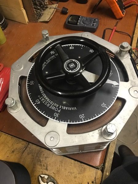
So I picked up a super sweet but heavy duty variac.
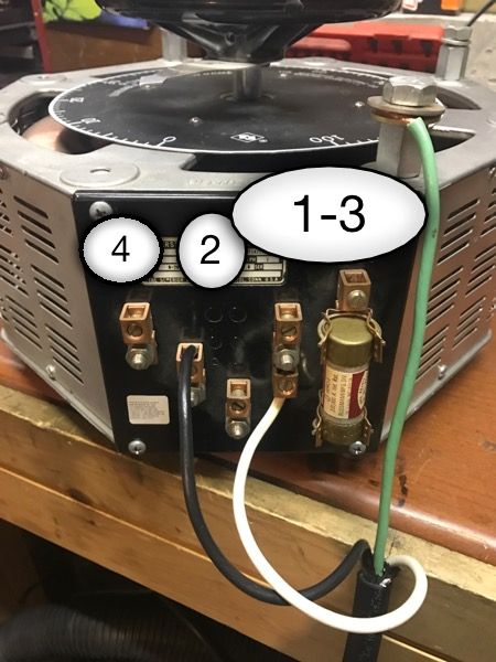
A Superior Electric Powerstat 1256D. 240vac 30A rated for 7.8kVA!
Look at this beast:)

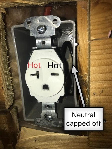
Now, a few years ago I had a professional electrician wire a 240vac 30amp breaker for my welding machine. I thought I would use this outlet to power the variac for my 240 volt needs. Just wondering if you guys minding advertising on the wiring.

There is a 4 wire cable coming in black-red-white-bare ground. The neutral in the box is capped off


I have 10awg SO cord to run from the outlet to the variac. I know the green ground wire obviously bolts to the frame but do I just connect the other "hot" to the neutral point?

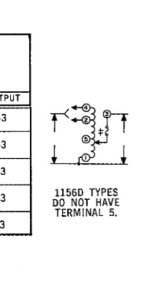
1 & 3 are your outputs #1/2 , 1/4 are your inputs. 5 (unlabeled) looks to be some center tap.
Wires from 1 & 3 will go to my load is this correct? Will this variac operate with no neutral ? The goal of this is to some day power 240 volt transformers or loads and using the variac to regulate that.
Example if I got a Europeans mot I could use this variac to power it. The problem I see is there is no neutral leg tied to the ground. Hmm. Am I completely confused here?


Last edited:
I would assume you have 120V between either of the "Hot" phases and the neutral and between the two "Hot" phase will be your 240V .

In the UK we have a similar setup for 230V / 400V , though this isn't seen in peoples houses

1 - 4 are the inputs , 1 - 3 are the outputs on that variac .
 
Last edited:
Ok, thanks, my wiring is correct. There is 120v on each side in relation to neutral. next to test it on step up XMFR. I have a 208-450 that should be a good candidate.
Thanks dash!
 
Last edited:
That's a NEMA 6-20 outlet. It's 20A rated, not 30A.

Of course, they're rated conservatively and will be fine at 30A, BUT you want to be sure the wire feeding the outlet is at least 10awg if it is inside a wall at any point, and that the breaker is also 30A. Either way, it's NOT UP TO CODE if this is hooked up to a 30A breaker. Run it at your own risk.

Inputs at 1-4 is for a 0-240V range. Inputs at 1-2 is for a 0-280V range. At least that's what is typical, given the diagram. Hard to say because you cropped out the important bit.

Good point Cyparagon. Good catch!
Yes, I was looking for that information too and wondered about it. :thinking:
 
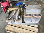
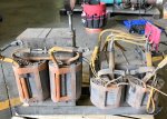
Hey folks, Im bit perplexed by this transformer configuration though I believe it's basic.
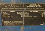
I pulled it from a very old miller welding machine and plan to use it as a ballast for a 10kvA pole pig. The core(s) seem to be large enough(100kg easy) where saturation will be less of an issue. It appears as though there are two independent transformers here or is one a primary and the other a secondary which I'm inclined to believe. I'm very far away from build the TC but this might be a good option for a inductive ballast whether I winding my own primary or use what's there short the secondaries in series. Can anyone point me in the right direction where I can learn more about transformers just like this?
I can tell from the name plate it steps down to 32V and the smaller coil has various taps for voltage input from the red bus bar.
 

Attachments

  • IMG_2807.JPG
    IMG_2807.JPG
    126.7 KB · Views: 30
  • IMG_2806.JPG
    IMG_2806.JPG
    114.3 KB · Views: 51
  • IMG_2808.JPG
    IMG_2808.JPG
    90.1 KB · Views: 32
Last edited:


Back
Top