Welcome to Laser Pointer Forums - discuss green laser pointers, blue laser pointers, and all types of lasers

Buy Site Supporter Role (remove some ads) | LPF Donations

Links below open in new window

FrozenGate by Avery

Possible 8X Sled from HighTechDealz

It goes straight up, without a kink, to failure. :thinking:

If this won't drive us crazy, nothing will :tinfoil:

Peace,
dave


It goes straight up, without a kink, to failure. :thinking:

If this won't drive us crazy, nothing will :tinfoil:

Peace,
dave

Yeah, until we got 6x's, the kinks at least told us where to stop..

Now it's a guessing game! And the only way to get results is by killing EXPENSIVE diodes! :cryyy:


I would love to test two more of these, and cycle them at more conservative powers - higher than i set most GGWs, but not too high. But i simply can't afford it anymore... I spent almost $400 for experimenting on worthless diodes in barelly over a month!

Well, unlike some other diodes, i don't consider these here worthless, but ~$90 is "a bit" too much...


At the same time i fear what i'll find once i calculate how much the good GGWs ACTUALLY cost me, due to all the weeding out of the weaklings i did... :undecided:
 
Last edited:
Even admitting that all they works like that graph, perhaps that you can at least use them as 6X substitutes, or very little few more, (say, 230 / 240 mA ?) ..... but you're right, with the actual market, probably the diodes themselves can worth 30 $ or similar, sure not 90 / 100 $ ..... Also for the risk to find ones that die at 180mA or similar.

Just a personal feeling ;)
 
I have a theory...

But first, can someone please tell me, if the S03 and the 203BK use beam-circumcisers? I mean beam-circuliser cubes, like the 4x's and the 6x's?
 
I have a theory...
But first, can someone please tell me, if the S03 and the 203BK use beam-circumcisers? I mean beam-circuliser cubes, like the 4x's and the 6x's?

The Pioneer S03 has a cube between the diode and the PBS cube.

The Pioneer 203 has a cube between the diode and the PBS cube.

The LG BH08 does NOT.

Peace,
dave
 
Hmm...

Ok, the v3 theory was discarded in the meanwhile for other reasons anyway (and the cubes are in favor), so i returned to my "original" (v2) theory...


In the beginnning, i used to think that the GGW uses the 105/210mW Sharp diode...

But later i saw Sharp announcing they are developing a 125/250mW diode for 6x BR Writer drives.. AFTER the GGW drive was already in production.

So the GGW drive might still have used the 105mW diode but with more efficient optics, OR a 120mW diode from Sony, which was already available at that time..


So now i'm thinking, that:
- the GGW perhaps uses a 125/250mW diode,
- the S03 a 140/280mW diode (or maybe 150/300mW diode at most)
- the 203BK a 175/350mW diode (or perhaps even 200/400mW?!?)
AND
- the SF-AW might be using the 105/210mW Sharp diode, which has a kink indicated in the datasheet at it's pulsed power rating (while all the others mentioned here have no kinks anywhere)


This would explain why many GGWs can survive being set to 200mW+ after plastics, where the raw power is around 250mW if not more!

It would explain why the S03 seems slightly tougher than GGW, but not that much. They must have reached 8x burning speeds with a more efficient optical train in that one..

And it would also explain why the 203BK's can relativelly "safelly" be set to 400mW+, never mind 500mW+, altho their life expectancy must be short in the latter case...


Of course ALL of the above is pure guesswork!


To make things more confusing, for some reason various manufacturers pretend the highest powers available for sale are 120mW or so... And they are never floating pin, but have a pin arrangement such as reds with a PD inside... :thinking: (of course for Writer drives PDs are not needed, and it would be a waste of money for the manufacturer to include them)


In the meanwhile i also found official data as to what power 4x SL and a 4x DL Writer drives need (60/120 vs. 85/170mW), and got a 2x and 3x Writer diode for testing.

Unfortunatelly my beloved cat decided that one of these two diodes was much more fun if it was kicked around on the ground, rather than being left in it's boxy on my table and has been MIA ever since.. :yabbmad:


Which reminds me, i should plot the diode my cat hasn't lost yet, just for fun, while i'm at it..
 
thanks for the good work, igor, and for shining some light in the dark! :-)

.. beam-circumcisers? I mean beam-circuliser cubes, like the 4x's and the 6x's?

never heard of that (since i dont have such sleds yet). any info on that? any name i can google? perhaps even useful for making a pointer more beautiful? (if its working like some fast-axis-correction)

manuel
 
You mean that optic cube you have to break off the front of the GGW diode casing?

Yes..

But I never break them off during diode extraction. I have bags full of GBW and GGW heatsinks with these cubes still on... Only in a few cases did they fall off...

I left them on so that i could try them out with different diodes, to see what kind of output they create...


never heard of that (since i dont have such sleds yet). any info on that? any name i can google? perhaps even useful for making a pointer more beautiful? (if its working like some fast-axis-correction)

manuel

I don't know their official name, but they are beam-shaping optics, there to make use of all of the diode's power.

Since unlike reds, the 405nm's are almost somewhat "multimode" - well, their outputs are horribly flat - most of the drives use these cubes to create a rounder beam, with the "cube" directly above the diode, before any other collimation. That way the drive gets to use more of the diode's power, because it's not getting lost at the sides of the fast axis anymore.

It is actually the same as FAC yes... It slows down the fast axis to allow the slow axis to catch up with it before collimation..


I wouldn't know how to use one in a pointer tho, and i don't know how they affect FL's, but they do create round-ish looking outputs from the flat ones we are used to.
 
Last edited:
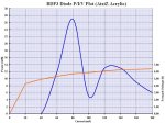
Oh, the 2x or 3x diode my cat hasn't lost yet made the funniest plot EVER!

Obviously it was a very low power diode - the Vf climbing rapidly being a good hint - and probably dead long before reaching the first peak, but oddly enough, the plot retained the same shape every time i went over it, even after going to 700mA, where it did a whopping 13mW..:crackup:


Of course with every attempt, the peaks were lower.. But the shape was constant! :thinking:
 

Attachments

  • BDP3 PIV Plot - LR.JPG
    BDP3 PIV Plot - LR.JPG
    204 KB · Views: 80
Last edited:
I left them on so that i could try them out with different diodes, to see what kind of output they create...

The cube in front of the GGW is a slow axis corrector + prefocuser ..... and is a damn pity that is so long :p :mad:

If only it was just one millimeter long, we can have a perfect focusing tool, just changing the house of the diode in the modules, damn hell ..... but i made some tests, and it's just a pair of millimeters too long for let you use a normal lens assembly for focus the beam in a microscopic extra-burning spot .....

I reached to focus it in a spot maybe 1/10 of the ones that you can reach with a good glass lens assembly, but just dismantling an aixiz glass and using a single lens (and, ofcourse, not using a diode holder, i left the corrector in place on the original diode holder, for the tests)..... and i got a point so tight that it burned white paper powering the led at just 70 mA ..... if only it was thin enough to be fit inside a common aixiz module (AAAARGH !!)

Other than this, they are individually-aligned ..... i mean, the alignment of the SAC axis depend from the position of the chip of the LD when it's in the holder ..... i tried to just put it on the top of a PHR, when i finally dismantled the GGW for put it in a module, but for get the same result, i needed to position it approximatively 1 mm away from the PHR surface, and align it carefully in both axis and rotation ..... i'm not sure that is possible to use them, once you took the original diode away, or at least, it require not-too-easy realignment with the new diode, probably.


Did any BDR-S03's die at as little as 180mA without being pushed much higher first?

I'm sorry, i don't know, cause actually i don't have any of them for test (and, being sincere, i don't have enough money, at the moment, for buy one of them just for destroy it).
 
The cube in front of the GGW is a slow axis corrector + prefocuser ..... and is a damn pity that is so long

Hmm, i haven't thought of that.. The slow axis really is slow!

But the fast axis is bizzare in comparison!

So if anything, the cube probably corrects both, to achieve a rounder output and allow the drive to use the entire power output.


Other than this, they are individually-aligned ..... i mean, the alignment of the SAC axis depend from the position of the chip of the LD when it's in the holder .....

I know it requires axial alignment, but the diodes only go in one way, if the heatsink is left in tact..

It does work with other diodes, altho since they have different beam profiles, the results are not always perfect..
 
Last edited:
Yes, if you look at it, the face against the diode is a negative cylinder lens, probably positioned with the focus on the surface of the chip, and the other face is a round positive lens, but with a too long FL for our uses.

The assembly, practically, "correct" the slow axis, enlarging it same as the fast axis, and the positive acts as "prefocus", making a near-to-good circle shape ..... but it's too far from the corrector, so a lot of power go lost at the borders and for internal reflections.

For this i say it's a pity, if only the positive was 1 mm or less from the corrector, catching all the beam, instead cut out only a circle from it, we probably had a "square" or almost square spot, with less divergence than the fast axis, ready to be focused at very small points or tight beams ..... ah, well.
 
Wait, so you don't think the fast axis is being corrected AT ALL with that cube?

Why would that be? I mean, i understand the need for "blowing up" the slow axis, as it really is flat, but the fast axis is even worse with these diodes.

If some FAC was used, a lot more power would become useful....


A friend tested this cube on a PHR and said he got a very nice oval output....
 
Uhm, probably they don't correct the fast axis, just cause, for readers / burners, the circularity and thin focal point are the more important things ..... i mean, after all, there are other optics and parts that "cut away" some other power, in the beam path, so they probably just preferred to have an already-round beam exit, for simplify the rest of the optic path (other manufacturers do the same thing using diaphragms, usually together with the diffraction gratings, like as example in the PHR sled)

And, after all, if you compare the beam passing (unfocused) through the 1 mm diaphragms of the PHR, or the 2 mm of some other sleds, with this output shape, you here already have much more light, also cutting away part of it from the fast axis :)

Anyway, looking at that corrector, i don't see any positive curvature, on the negative correcting face, so, i think the fast axis is not corrected at all, at the diode output, just prefocused with the slow axis from the final positive lens on the opposite face.


Back
Top