Welcome to Laser Pointer Forums - discuss green laser pointers, blue laser pointers, and all types of lasers

LPF Donation via Stripe | LPF Donation - Other Methods

Links below open in new window

ArcticMyst Security by Avery

OSRAM 60W multilaser chip with 24 beams - JLM450nm

Joined
Feb 12, 2016
Messages
589
Points
63
Finally received the Multi laser chip apparently made in China by Osram.


It looks very similar to NUBM31T but unlike that one cannot be found on ebay, aliexpress nor taobao.
I read that this kind of devices are called Butterfly chips.

This one comes from Alibaba (I paid 240EUR for it) and was said to be 60W. It has 24 lasers packed very close but is smaller than NUBM31 from Nichia according to data sheet. And it has no documentation with it. Maybe it does not even oficially exist but now it is here before my eyes!

So first of all I have quickly tested it to find out the polarity of the pins. Was surprised to find out that 2 upper rows had + on the right and 2 other rows on the left. The strong light started already at 200mA unlike NUBM44/08 which need at least 400-450 mA current to really ignite.

The beams from each row looked at first sight very parallel, at least as parallel as beams from a NUBM08 block. The glass multilens is well fixed on the body but is not hermetically attached and it is even possible to insert a paper between the brass body and the glass.

I want to test all beams at full power but first I am doing the HS and would like to find the right plugs now. The chip wires seem to be 0.4mm thick like in common LDs and they can be inserted into common LD sockets or into female power plugs for LEDs found in Kasio projectors. This makes a good contact.

Can anyone indicate me where to find single sockets for these wires (because these LD sockets on picture have 3 holes and are pretty big in diameter)? Or where could I find these type of plugs in order to insert all 4 wires into the holes? I would need a plug like on the picture but longer.
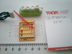


Osram JLM 450 nm small.jpg


WizardG

0
LPF Site Supporter
Joined
May 9, 2011
Messages
1,170
Points
113
I'd be worried about the longevity of the die in that package if it's not airtight :(
 

likevvii

Member
Joined
Mar 2, 2020
Messages
74
Points
18
What is the reason why you picked this array over the 31T? Does it have better mounting tolerances for each diode?

I am looking to buy a 50W+ array to focus at 200mm away. Thank you for bringing this specific model up. It is quite interesting.
 
Joined
Feb 12, 2016
Messages
589
Points
63
I picked it exactly because it is not 31T. Something different and cheaper.

And I want to check it because no one will report me about these tolerances before I check them by myself.
 

likevvii

Member
Joined
Mar 2, 2020
Messages
74
Points
18
Thanks for doing this to test.

Based on what you have read so far, which one do you think has better precision? How does does all the beams measure at a distance?
 
Joined
Jun 20, 2015
Messages
244
Points
43
I picked it exactly because it is not 31T. Something different and cheaper.

And I want to check it because no one will report me about these tolerances before I check them by myself.
Power that sucker up and give us some pics and info on the behavior of the beams!!! :0)
 
Joined
Feb 12, 2016
Messages
589
Points
63
Styro purchased his 31T in summer and did not yet post any spot picture. Then DashApple...

And from me you guys want to power all assembled just a little over a month after receiving the bare chip without any specs info available? This does not work so fast! Up to now I found right contacts, the HS is being polished in a workshop, but I still do not have a proper power supply up to 115V (could use a coulple of 80V maybe).

Indeed I wanted to make an ice cooled gun (from a disassembled ice cream maker) to keep the T close to 0ºC for at least one minute of beaming (until ice melts). This will not look like you expect but could give maybe even as much power as 95W chip does without cooling. Because its efficiency could sharply fall with rising T...
 

likevvii

Member
Joined
Mar 2, 2020
Messages
74
Points
18
I apologize for trying to rush you.

If you are unable to power all diodes, maybe you can power each array and then overlap the 4 images?
 
Joined
Feb 12, 2016
Messages
589
Points
63
Ha, you are using same words what I have used to ask styro, DashApple and other members who bought 31T to post a spot picture!

Not yet there. Even for one row I would make a proper HS+driver set up.
 
Joined
Feb 25, 2010
Messages
1,643
Points
113
Styro did post on Youtube on 3.13.2020

See here.....

THIS is a funny video !!! His build methodology is just a Hoot !!....I called his method....." KISS-Centric " LMAO
His machining methods are....well....simplistic....but seemingly effective !!! I applaud his sense of humor and hubris !!!!

Anyway....The beam alignment looks OK....Hard to tell....as he only has a Mid Field beam target of about 12M max.

He really keeps the build simple !! Only a large cylinder of Aluminum for cooling.....and NO Fan or external radiator fins. SO....One could NOT get much more KISS than this !!!!...He DOES have on-board temp and LiPo pack monitoring.....Good plan !!!

So twenty four beams !!! 95W !!! 5~7 minute run time....Hmmmm...a Hand Held " Real Genius " special....Come to think of it....THAT is what I would have named this build !!!! RG-1 !!!..." Small, Compact, Extremely limited run time "...." Let the Scientist's figure out a use for it " Hahahahahaha !!

So....Vlad....Power that Bad Boy up....and let us share in the excitement !!! THANK YOU Vladimir and Styro !!!

CDBeam
 
Last edited:
Joined
Feb 12, 2016
Messages
589
Points
63
Hi Bob,

I saw it and I even ordered some of these radar bodies to check how big they are. However, I do not know where they would arrive because our Campus is now closed for 2 weeks (or more?) quarantaine and there is no one at goods reception any more.

It is good that Styro shows the inside sructure but in his videos he gives no info about dimensions.
If Al cylinder is 80mm in diameter as it looks to me then maybe this square body would be OK for the design I am thinking about.

But I need NUMBERS! And there are no NUMBERS in comments to this video!!!

Also I doubt that using In (mp=150ºC) foil would give advantage over thermal paste - has anyone tried it for CPU, TEC?
I think the right material has to be liquid at thermal transfer time like Ga is. But Ga dissolves Al so cannot be used here.
 
Joined
Feb 25, 2010
Messages
1,643
Points
113
Yea...Styro is not big on numbers !!! HAHAHA !!! BUT....He did pop SIX (6) Ballloons !!! And Burn ONE (1) steak HAHAHAHAHA !!!!
It amazes me that he made NO provision to dump heat from the Ally cylinder to atmosphere....a small fan would help.......attached external to the Radar Gun case !!!!..OH...and...That would add to the " Steampunkett " look !!!

But then...just how long will be the power-on time be in this ....or any other HH application ??? Not Long...5~10 second bursts.. ...maybe 4 bursts per minute....Just my guess !!!

Anyway...looking forward to your " First Light " event !! Stay safe and healthy....to ALL of us !!!! Bob
 
Joined
Feb 12, 2016
Messages
589
Points
63
Hi Bob,

Here you have your "First Light"

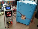
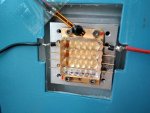
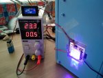
Finally I made a robust setup with "water cooling" to test this 24 beams array.
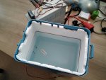
Not a current of water as you see but simply an Al tank with water, which would heat as the array is working. Made of a cheap party fridge from ali which only had one crappy small TEC inside. Anyway there will be no parties because of corona for the next 2-3 years...
Also made solderless contacts in order not to have to solder at the butterfly chip wires directly.

If 2-3kg of ice were put in this tank, I think the array could beam long long at full power. I just have to add a discharge tap for hot water...
Anyway I do not have a 110V driver to test all LDs at once, so only tested each row of 6 beams one by one now.

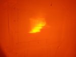
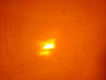
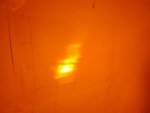
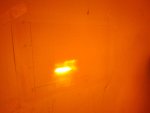
Here you can see that all beams are pretty well collimated by stock multilens (lines on wall 5m away) but beams orientation if worse than it was at NUBM08 block I tested 2 years ago.

The 1st (top) row gives the worst spot, 4th (bottom) row - the tighest spot. Other rows are somehow in between.

PS: How bad is the millimeter paper of today, before it was made with much more contrast lines!!!

Osram 01.jpgOsram 02.jpgOsram 03.jpgOsram 04.jpgOsram 05 1st top row 0.5A.jpgOsram 06 2nd row 0.5A.jpgOsram 07 3rd row 0.5A.jpgOsram 08 4th bottom row 0.5A.jpg
 

likevvii

Member
Joined
Mar 2, 2020
Messages
74
Points
18
Thanks for the beam shots.
Some weird stuff going on. It is as if the multi lens is not correctly focusing or possibly the diodes do not all have the same Z height?
On the 3rd picture, you can see some kind of "split beam" all the way at the top. I wonder why it does that.

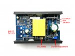
You may find this to save you a quite a bit of time; there is $50USD driver floating around Chinese manufacturers rated at :
85Vout, 3.3Amax
0-20Khz
0-5V TTL
9~14V input
*I was not able to find the efficiency curve.

These are specifically designed to power the osram and nichias. Almost all of the companies that sell the arrays also have this, but I had to dig it out of them because it is not an official product. Some sellers ask up to 100USD, lowest I've got offered is 50.
I wonder what was the reason they chose such a low 12V to be the input voltage.

array driver.jpg

___

Interesting to see your cooler progress. How large of a battery do you think will be needed to match the thermal capacity of the ice? I've purchase some 21700 cells to make a battery pack and realized even 12 of them in series would only last 25mins on max for the nichia.


Top