Welcome to Laser Pointer Forums - discuss green laser pointers, blue laser pointers, and all types of lasers

LPF Donation via Stripe | LPF Donation - Other Methods

Links below open in new window

ArcticMyst Security by Avery

OPEN SOURCE: "CC-Boost" - 2.4 Amp boost driver - RC1

Joined
Jul 4, 2012
Messages
2,834
Points
63
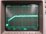
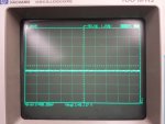
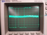
Finally received the last of the components yesterday and put together a board. Output seems fine when checking with a multimeter, but further inspection with a scope shows a lot of oscillation. This occurs both when powered via battery (18650 panny) or power supply (voltage set at 4.1V, no current limiting). Voltage across a 0.1 ohm resistor was scoped. Dummy load was set to drop ~4V. IC and inductor get warm after ~30 seconds, but nothing unusual. Can easily hold finger on them. Occasionally it will be steady for a few seconds and then start oscillating (while emitting a high-pitch tone). Any suggestions?

Scope pics can be seen here: https://imgur.com/a/pZDuo

Well for one thing you are supplying a higher voltage than you are dropping, so it isn't actually boosting. Try setting your load to 4.5-5V
edit: for your PSU, that is.
 
Last edited:


rhd

0
Joined
Dec 7, 2010
Messages
8,475
Points
0
Well for one thing you are supplying a higher voltage than you are dropping, so it isn't actually boosting. Try setting your load to 4.5-5V
edit: for your PSU, that is.

Good catch!

Switching regulators need a bit of a margin to, so you don't want the output drop to be "just slightly" above input, there needs to be a meaningful margin.
 
Joined
Sep 22, 2007
Messages
169
Points
18
Well for one thing you are supplying a higher voltage than you are dropping, so it isn't actually boosting. Try setting your load to 4.5-5V
edit: for your PSU, that is.

Ah, that would make a lot of sense. I knew I was probably overlooking something obvious. I'll give that a try at work tomorrow and report back.
 
Joined
Jan 29, 2014
Messages
12,031
Points
113
I wonder what is causing the oscillation, you too I am sure. High frequency spikes can sometimes be absorbed by tantalum capacitors, they can handle smoothing out high frequency components where other types can't. Do you think the spikes are due to feedback induced through the leads of the circuit board, resonances or capacitive feedbacks induced through having everything so close together, or something to do with the physical orientation of parts causing coupling that wouldn't exist otherwise? Perhaps the nature of the IC's design requiring capacitive bypassing?

Please don't beat me with a wet noodle for speculation alone, sometimes this can lead down the right path, even if I have not had the pleasure of working with this design yet. I want to, it would be a great learning experience if nothing else.
 
Last edited:
Joined
Sep 22, 2007
Messages
169
Points
18
I wonder what is causing the oscillation, you too I am sure. High frequency spikes can sometimes be absorbed by tantalum capacitors, they can handle smoothing out high frequency components where other types can't. Do you think the spikes are due to feedback induced through the leads of the circuit board, resonances or capacitive feedbacks induced through having everything so close together, or something to do with the physical orientation of parts causing coupling that wouldn't exist otherwise? Perhaps the nature of the IC's design requiring capacitive bypassing?

Please don't beat me with a wet noodle for speculation alone, sometimes this can lead down the right path, even if I have not had the pleasure of working with this design yet. I want to, it would be a great learning experience if nothing else.

My initial guess would be that it is due to the internal switching in the IC. Assuming the low voltage drop is the issue, it would make sense that the switching isn't being regulated correctly since it's not seeing the voltage drop it's expecting. Could be something else though; I'm mechanical, not electrical so I'm still learning a lot.
 
Joined
Jan 29, 2014
Messages
12,031
Points
113
Wish I could get knee deep into this troubleshooting, I've always solved every problem I've put my efforts into with circuits in past, but there is a steep learning curve for me on this kind of thing. Is there a single web page with all of the resources on this project at one location where I could download the project to make it easier to get what I need? If not, I could make one. I have a web page set up for that kind of thing to upload files to, put them in folders allowing downloads. Only thing I can't store are zip and exe files.
 
Joined
Sep 22, 2007
Messages
169
Points
18
Wish I could get knee deep into this troubleshooting, I've always solved every problem I've put my efforts into with circuits in past, but there is a steep learning curve for me on this kind of thing. Is there a single web page with all of the resources on this project at one location where I could download the project to make it easier to get what I need? If not, I could make one. I have a web page set up for that kind of thing to upload files to, put them in folders allowing downloads. Only thing I can't store are zip and exe files.

That's not a bad idea. Maybe start a Github for this driver? That will make it easier to keep track of revisions, post scope shots, troubleshooting tips, etc.

If you're looking for learning resources, I found this site pretty helpful: Switched Mode Power Supplies
 
Joined
Jan 29, 2014
Messages
12,031
Points
113
Thanks, I've worked on switching power supplies supplied by line voltage in the past and they can be beasts to tame, square waves producing infinite harmonics and all but for a switching power supply/regulator that is mostly inside an IC ought to be far easier. Maybe it is just the resistance you mentioned, but if not that and due to proximity of components, a thicker layer (or a copper plane inside) to put more space between the top and bottom might be something to look at, but that doesn't appear to be the problem from what is being shared here.

Thank you for the link, good info.
 
Last edited:
Joined
Jul 4, 2012
Messages
2,834
Points
63
Whats happening with the EUP boards? Anyone doing anything with them? I have a bit of spare money, I would be open to making a few and shipping them to someone with an oscilloscope.
 
Joined
Sep 22, 2007
Messages
169
Points
18
Update-

Retested with a voltage drop just over 5V and powered by a battery at 4V (power supply maxes out at 3A and it was saturating with lower supply voltages). Also added some heatsinking to the IC and inductor. Apologize for the old-school oscilloscope, nice one is in use by someone else currently. This was with the driver set to 1.88A. Seems to be working fine now, some noise still (~50mV), but reasonable.

Here's the odd thing: if I try to lower the current, it will stop regulating once it gets below about 1.7A. It will just go back to the behavior of the previous scope shots I posted.

Ideally, I'd like to run at 1.5A so it'd be nice to figure out why this occurs. The voltage drop at 1.5A with my dummy load is still over 5V, so that shouldn't be the issue unless it requires a larger margin. I hope this isn't the case, because it looks like the M140 drops about 4.5V at 1.5A and I'd like to run it off a charged 4.2V battery.
 

Attachments

  • scope_1880mA_4V.jpg
    scope_1880mA_4V.jpg
    374.1 KB · Views: 138

benmwv

0
Joined
Sep 10, 2010
Messages
1,380
Points
48
Think you could redo that test, measuring the voltage over your test load resistor instead? Since the purpose of the driver is to regulate current, it would be more helpful to have a current graph imo.
 
Joined
Sep 22, 2007
Messages
169
Points
18
Think you could redo that test, measuring the voltage over your test load resistor instead? Since the purpose of the driver is to regulate current, it would be more helpful to have a current graph imo.

Sure, see attached.

Some more strange observations:

The driver whines until I adjust the output current to >1.7A and at this point the Rset should be ~470 ohms. However, I'm measuring it to actually be around 320. If I try setting it higher, the output drops below 1.7A and then starts oscillating again.

The power is now adding up. Running off a single 18650 at 3.9V, it pulls just under 4A. Thus, 15.5W into the driver. At the output, it is 5.5V at 1.75A -> 9.6W. Unless this driver is only 60% efficient, something else is clearly wrong with my board.
 

Attachments

  • scope_4Vsupply_45Vdrop_resized.jpg
    scope_4Vsupply_45Vdrop_resized.jpg
    399.1 KB · Views: 97
Joined
Sep 22, 2007
Messages
169
Points
18
I tested a second driver I assembled; same issue. There appears to be a "threshold" current below which it will not boost properly.

For this driver, the threshold Rset is 412 ohm. Just below this, it outputs a clean 1.89A (startup shown in attachment). Just above that, and the output oscillates between ground and Vout at a frequency which decreases as Rset increases. In other words, the whine gets higher and higher pitch as Rset is lowered until it finally goes away and the output is stable.

I guess as long as I stay >1.9A I will be fine, but I'd really like to drive the M140 about 1.5A. Also, I'm really curious why this is happening. It's the curse of the engineer ;)
 

Attachments

  • D1_375Vbatt_47Vdrop.jpg
    D1_375Vbatt_47Vdrop.jpg
    441 KB · Views: 124

benmwv

0
Joined
Sep 10, 2010
Messages
1,380
Points
48
If I'm reading this right something is seriously wrong!

Two things are really concerning me.
First there is approx a 500ma spread in the ripple in that first pic! Jumping between 1.5-2A is not acceptable. The second pic, while not as bad, is still pretty bad. An m140 would probably handle that but if you tried to run it hard I'm sure those spikes would kill it.
Second, why does the ground have so much ripple in the last pic you posted? That first bit is before the device was even turned on, it should be flat!

In laser drivers I consider acceptable ripple to be around 5%. This is more like >25%, and I think that definitely means there is some sort of problem, probably the same thing that is causing the low efficiency you mentioned. I'm thinking this might be inductor related? Since you said there was an audible whine.
 
Joined
Sep 22, 2007
Messages
169
Points
18
If I'm reading this right something is seriously wrong!

Two things are really concerning me.
First there is approx a 500ma spread in the ripple in that first pic! Jumping between 1.5-2A is not acceptable. The second pic, while not as bad, is still pretty bad. An m140 would probably handle that but if you tried to run it hard I'm sure those spikes would kill it.
Second, why does the ground have so much ripple in the last pic you posted? That first bit is before the device was even turned on, it should be flat!

In laser drivers I consider acceptable ripple to be around 5%. This is more like >25%, and I think that definitely means there is some sort of problem, probably the same thing that is causing the low efficiency you mentioned. I'm thinking this might be inductor related? Since you said there was an audible whine.

This particular scope is old and doesn't give a real clean signal anymore. The ground noise is around 30mV. I'm going to retest it tomorrow on the better scope.

I guess next step will be to start scoping individual components to see if I can find something usual. I'll start with the inductor. Next, maybe look at the feedback signal going into the IC.

I'm still concerned about the power draw. I would think the efficiency should be >80%, not ~65%?


Top