Welcome to Laser Pointer Forums - discuss green laser pointers, blue laser pointers, and all types of lasers

Buy Site Supporter Role (remove some ads) | LPF Donations

Links below open in new window

FrozenGate by Avery

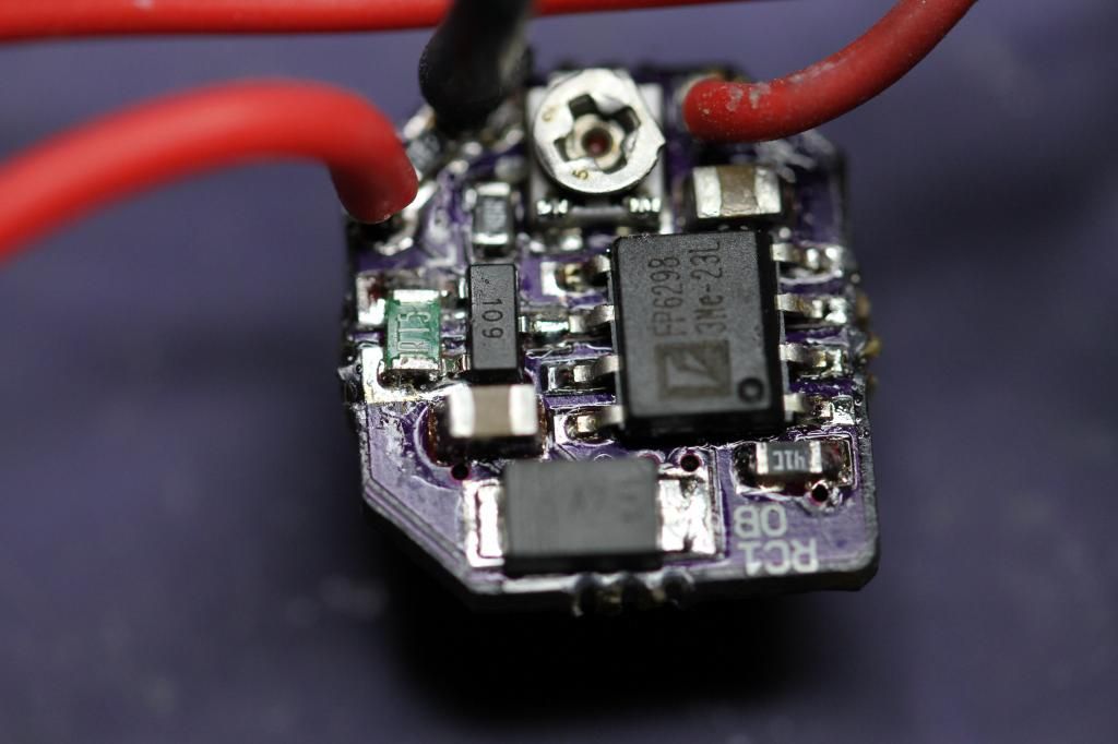
OPEN SOURCE: "CC-Boost" - 2.4 Amp boost driver - RC1

I was thinking most drives at these currents were recommended to be heatsinked.
It's really not that big of a deal to me. I wouldn't want to try and fit it in a really small host but something like the "Big Chunk" host works great. I just stick the inductor to the module heatsink and a strip of copper from IC to host. Works for me. YMMV. :)

Heatsinking or not though, the current on his drive isn't hitting 2.4A - so there's something wrong, regardless of the heat issue.


Heatsinking or not though, the current on his drive isn't hitting 2.4A - so there's something wrong, regardless of the heat issue.

That's true. My thought was with heat sinking the drive may function long enough to figure out what's wrong. Maybe not. :)
Edit: I'll try and find time this weekend to play with the one I have. See if I can figure out something. Worse that can happen is I let the smoke out of it. :)
 
Last edited:
Rhd, your drive cleard customs, so you should have it relatively soon.

Oh cool ! I didn't know you sent one to rhd. Problem solved. Be interesting what he finds. I hope I don't have to issue a recall on my lasers. :crackup:
 
My guess is he will find the problem is not in my assbling the driver, contrary to [popular] belief.
 
Last edited:
So, I have good news and ... confusing (?) news.

The good news:
I really wanted to find a problem with the driver's assembly. I looked really closely, tested the resistor values, tested the cap values as best I could, and did some conductivity tests to make sure everything that was supposed to be connected was, and everything that wasn't, wasn't. After all of that, I didn't find anything wrong with your assembly. In fact, I think it was a pretty good assembly job!

The confusing news:
When I tested the driver's operation, I couldn't find anything wrong with that either:

Video - TinyPic - Free Image Hosting, Photo Sharing & Video Hosting

It output 2.26 Amps on boot, and was finger comfortable (ie didn't get uncomfortably hot until) about the 40 second mark. At that point, 40 seconds in, the current had dropped from 2.26 Amps to 2.1 Amps. In terms of 2.26 Amps, that's just the best I could do with the precision of the pot. Half a degree in either direction might have gotten us to 2.3 Amps, or whatever your target was, I don't know. I was even running the driver's output through quite a bit of wire (the test load wires as well as my DMM leads, because it was in Ammeter mode). I'll note that I adjusted the pot with the driver OFF, by simply measuring the resistance, and trying to get it as low as possible. I found that to be a whole lot easier than trying to adjust the pot while the driver was running (I hate pots).

So what's the issue here? I believe my comment in the very first post in this thread was that the driver "actually runs fine for a bit without any heatsinking". That seems pretty bang on to me, no?
 
Last edited:
Well, if it's not the driver it must be due to a difference in something else, perhaps power sources or test loads.
 
Last edited:
So, I have good news and ... confusing (?) news.

The good news:
I really wanted to find a problem with the driver's assembly. I looked really closely, tested the resistor values, tested the cap values as best I could, and did some conductivity tests to make sure everything that was supposed to be connected was, and everything that wasn't, wasn't. After all of that, I didn't find anything wrong with your assembly. In fact, I think it was a pretty good assembly job!

The confusing news:
When I tested the driver's operation, I couldn't find anything wrong with that either:

Video - TinyPic - Free Image Hosting, Photo Sharing & Video Hosting

It output 2.26 Amps on boot, and was finger comfortable (ie didn't get uncomfortably hot until) about the 40 second mark. At that point, 40 seconds in, the current had dropped from 2.26 Amps to 2.1 Amps. In terms of 2.26 Amps, that's just the best I could do with the precision of the pot. Half a degree in either direction might have gotten us to 2.3 Amps, or whatever your target was, I don't know. I'll note that I adjusted the pot with the driver OFF, by simply measuring the resistance, and trying to get it as low as possible. I found that to be a whole lot easier than trying to adjust the pot while the driver was running (I hate pots).

So what's the issue here? I believe my comment in the very first post in this thread was that the driver "actually runs fine for a bit without any heatsinking". That seems pretty bang on to me, no?

You have got to be shitting me.
Thats it, I am shipping all my drivers to you. They obviously fix themselves on the way there :crackup:
This was using how many diodes on your test load/what Vdrop? I had mine running at 5.2V out (measuring current with with one meter and voltage with another). Measuring both wouldn't cause problems, would it? Can't imagine it would.

Would you mind throwing together a board using one of the IC's I sent you? See if anything odd happens.
 
HA ! My first toaster oven drive :) Thanks rhd, I used so little solder paste I thought no way that will work. It was so cool to watch it melt and flow.

This one works too :)
 
Would you mind throwing together a board using one of the IC's I sent you? See if anything odd happens.

I can't really see how that would be helpful? The IC on your board was an IC that you sent me and it worked fine.

To be frank with the forum, I don't really want to invest more time into this driver. I got it out there, so that the forum would have something to work from, but I hate both boost drivers, and adjustable drivers, so this driver annoys me on several fronts every time I see it ;)

I have a whole bunch of the EUP chips that I ordered but never used. If anyone wants to start working on the version 2.0 design, let me know. I'll drop some of the chips in an envelope, and you can take the boost train forward :)

I think the EUP based driver is the future of the CCBoost. The higher frequency means smaller inductors, with potentially less resistance, heat, all that good stuff.

I may be down too. Though it probably makes more sense for you to send it to someone closer (plus I won't be of much help anyway, not much I can do besides build them).

Do you know of any places that are a bit cheaper than oshpark? I got nailed on shipping from oshpark and oshstencil, it was like 500% of the item cost lol. How does one go about calculating Rset? The schematic file has calculations for if Rsense= .075 or .015, but the schematic itself (using .06ohm and .12 ohm Rsense resistors) is .04 ohms...so...wat?
Furthermore, does it matter what for resistors are used for Rsense (thick film vs metal foil)?

I just wish I knew what the crap is wrong with these darned things. I'll ask again- what were your test load settings? I just tried all the drivers i have built and they all are still misbehaving. Same with the one I sent you, only somehow it magically works now.
 
Last edited:
I may be down too. Though it probably makes more sense for you to send it to someone closer (plus I won't be of much help anyway, not much I can do besides build them).

Do you know of any places that are a bit cheaper than oshpark? I got nailed on shipping from oshpark and oshstencil, it was like 500% of the item cost lol. How does one go about calculating Rset? The schematic file has calculations for if Rsense= .075 or .015, but the schematic itself (using .06ohm and .12 ohm Rsense resistors) is .04 ohms...so...wat?
Furthermore, does it matter what for resistors are used for Rsense (thick film vs metal foil)?

I just wish I knew what the crap is wrong with these darned things. I'll ask again- what were your test load settings? I just tried all the drivers i have built and they all are still misbehaving. Same with the one I sent you, only somehow it magically works now.

You're right, the EUP board had some inconsistent RSENSE numbers. I just cleaned up the board and made an easier version for testing purposes. I sent it to IWIRE, but I may as well share it with everyone. It also contains a spreadsheet for calculating RSETS:

http://www.filedropper.com/aanewopenboosthcv04

I don't know why you got dinged on shipping from OSHPARK. I'm in Canada, and shipping has always been entirely free to me. I assume its free in the US too, no?
 
Last edited:
Ah yea it was, I was thinking of oshstencils. Eh, whatever. Also I think the link you were looking to post is this one: http://www.filedropper.com/aanewopenboosthcv04

Also, for the .08ohm Rsense, why not just use 2 .16ohm resistors. Finding a .17143 ohm resistor to go with the .15ohm seems a bit silly :)
 
Last edited:
nope. I think it was like 7-8$ last time, cant be sure though. Also I think the link you were looking to post is this one: http://www.filedropper.com/aanewopenboosthcv04

thanks!

shipping should be free:

attachment.php
 

Attachments

  • osh.png
    osh.png
    61.1 KB · Views: 201
Last edited:


Back
Top