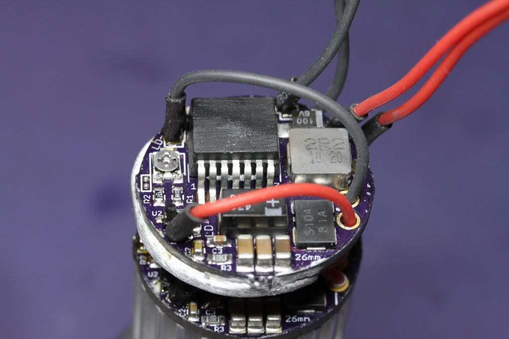
This is excellent information regarding powering up the higher power 9mm diodes. Definitely make sure all the components
can handle high current draw including the tail switch..
Use high temp (Silicone) wire only, preferably 20ga or better !!
Isn't that the truth. I'd be happy if I just knew the stuff DTR forgot :crackup:
Never met the man but I have a lot of respect for him and his willingness to share information. If he knows, he tells you. If he doesn't know, he tells you he doesn't know. I'm always going to his diode tests when something doesn't seem right just to compare to what he got.
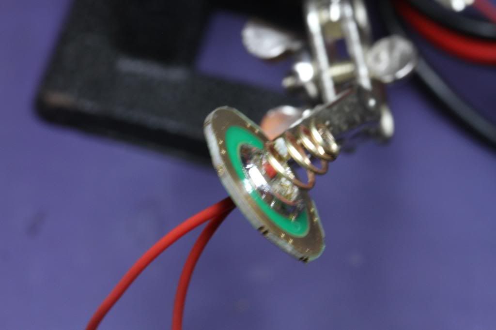
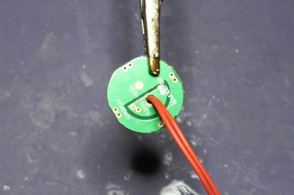
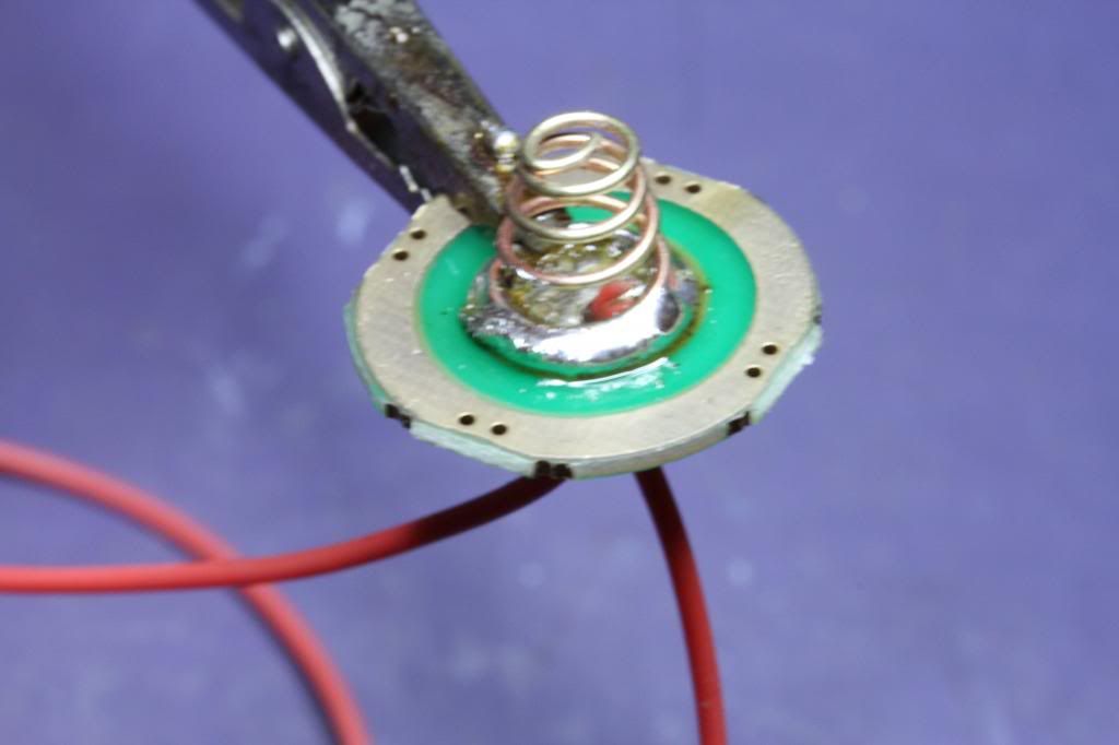
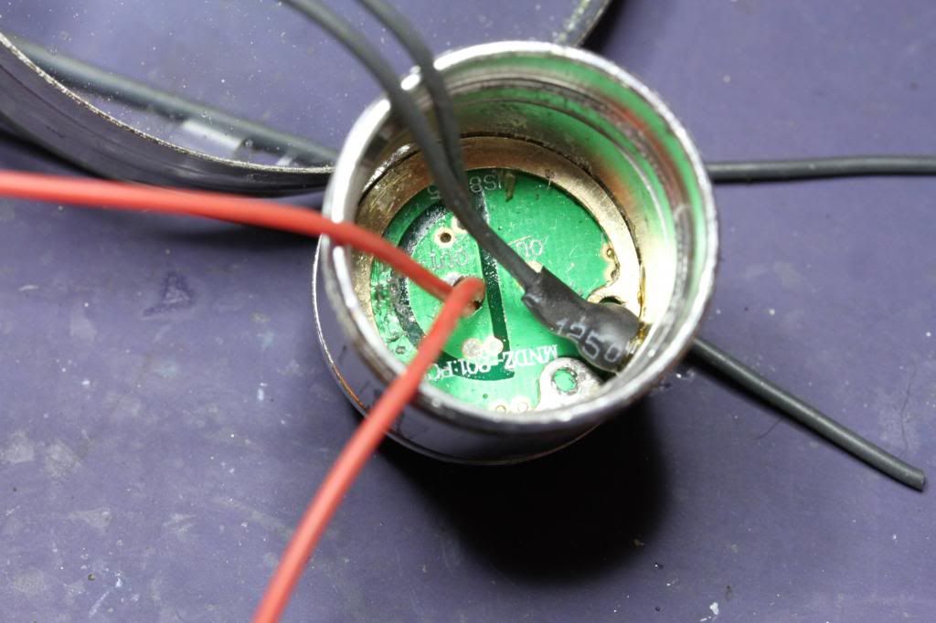
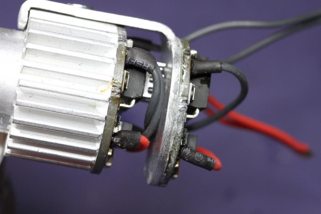
I got started on my battery contact. First thing I did was remove everything and clean up the old solder. Then I tinned the pad the spring sits on and tinned the bottom of the spring and remarried them together. Then I drilled a hole through the contact board where I wanted my wires. I stripped my wires back long twisted them together and soldered them. Put them through the contact board, wrapped them about a 1/3 of the way around the base of the spring and soldered them to the spring for maximum smoke generating capabilities.
")
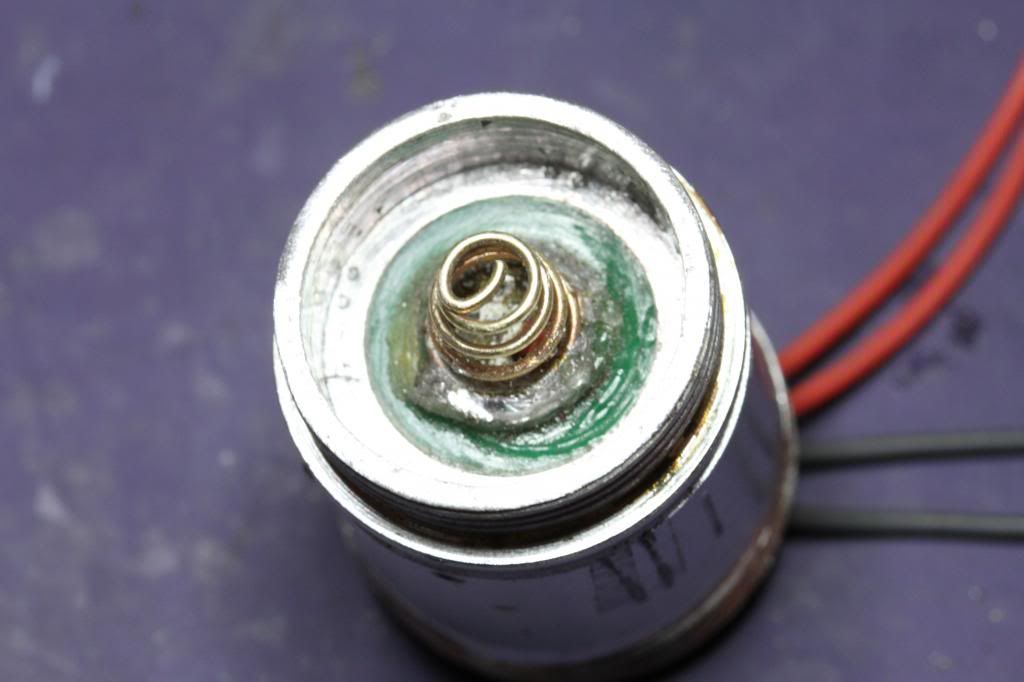
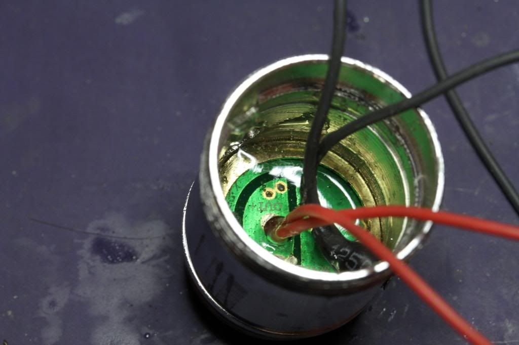
Since I'm not going to be using the ground ring I epoxied the contact board into the housing
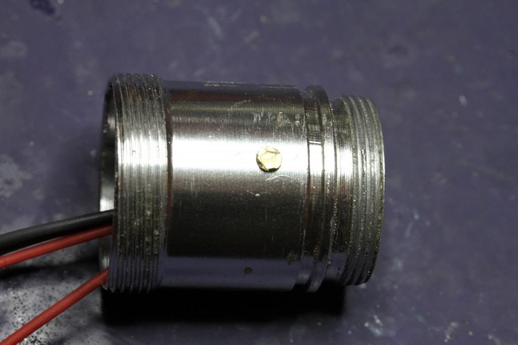
I drilled and tapped a 4-40 hole, installed a bolt and cut it off for a ground lug
I didn't have a groove for the snap ring but installed it anyway to help support the board and to keep the battery tension from moving the board. I thought about making a plastic spacer and using the stock snap ring groove but wanted the space I gained by doing it this way. I gained a 1/4 to 1/2" of room. This host has a ton of room. I soldered my 2 ground wires to my stud.
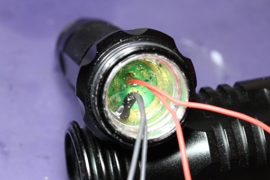
Then to make sure everything stays put I coated it with a layer of epoxy.
I tested it with an ohm meter and it tests good.
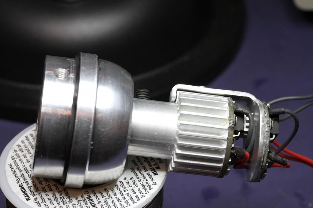
Ha ! Ol' Smokey lives ! :crackup: Almost all back together
You silly host, you can't kill the Rooster :crackup:


