Welcome to Laser Pointer Forums - discuss green laser pointers, blue laser pointers, and all types of lasers

Buy Site Supporter Role (remove some ads) | LPF Donations

Links below open in new window

FrozenGate by Avery

New High Power Red VSHIO HL63283HD LD


Yes, Techhood, Newgazer and Existotem are all the same company. Been that way for a long time. :yh:
 
That's how long I haven't been buying from anyone but Techhood.
 
Well....Sounds like you completely understand the very demanding nature of near perfect alignment with these C-Lenses !!!

The alignment....is just a bitch....and....when you shrink the build down....you have even more a challenge !!!:(:(:(

I wouldn't say completely.
The project I posted about this weekend is my second try with cylindrical correction optics. One difficulty that I never mentioned was just getting the will to bite the bullet and buy some good coated optics.

Good luck !! I still say...throw a EFL2mm Coli in the pot !!! The closer to the junction....the quicker the optical correction occurs....and the better the final results....which....are far from perfect....but....acceptable !!

Oh...Yea...I have run into alignment problems with the Press Fit Module !!!..They are the smallest package....They are inexpensive.....They provide likely the best Thermal Transfer from LD to Module Case....BUT....4 alignment....they can suck !!!

I do have some short FL aspheric collimators that I am trying out for other projects so I may throw (i.e. carefully and precisely position) one in the assembly. One complication with that is that it will change the focal distance of the cylindrical lenses which may interfere with the correction and may necessitate a different optical setup altogether.

But I've been thinking and I am planning to experiment with this:
Why not use one cylindrical lens to collimate the fast axis to match the divergence angle of the slow axis and then collimate with a PCX or aspheric collimator?
This, if it works the way I'm thinking, should give a square beam with a relatively large, but not unmanageable, diameter at the aperture.

Well, I ordered one of these diodes and will report my experiments with it.
1.2 W of 638 sounds like it'll be a lot of fun.
Looking at the numbers from the data sheet, with 1.2 W out and 2.3 V * 1.3 A (2.99 W) in, this diode approaches 60% efficiency!

When you get some data points, I'd love to add them to my efficiency plot.
Unfortunately, I don't have the equipment to properly chart the PIV curves.
 
Last edited:
Hi CDBEAM and RA,

After you started to play with this strange new red LD I also wanted to try.
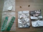
When asking a chinese friend to bring me some brand new PCBs for NUBM08 blocks (these PCBs are very cheap but only available on taobao, not on ebay) I added a couple of these HL63283Hd to the order. Taobao is cheaper than ebay, so I payed 130EUR for 2.

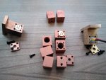
Now his parents arrived to visit him and brought the package. Interesting that after trying to insert them into various mounts it looks that LSP ones have bigger insert holes than those cheap tiny copper mounts from ebay Red Cowboy noticed recently. Only in 2 from 8 I purchased 9mm LD enters without pressure.

Now back to subject.
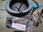
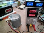
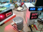
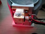
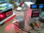
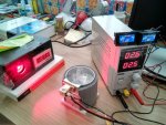
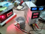
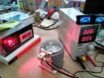
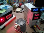
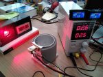
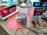
1st LD was burnt very quickly when I tried to drive it without cooling. Then with 2nd one I decided to play with real cooling and since I have no regulated TECs I use an old Al body from disassembled TEC drink can cooler. The experimental setup in this way was its ice filled body with LSP mount screwed to it bearing 2 temperature sensors. Yes, I also wanted to compare the 10kOhm NTC sensor from Lasertack with the one taken from aliexpress "wine bottle cooler and warmer" (a bigger and newer version of that TEC can coolers). The sensors were symmetrically attached with adhesive tape to both sides of the mount body, I also used a kind of chinese "Arctic silver" our IT colleagues use at work. Maybe to glue them with a kind of thermal adhesive would be more adequate but I do it for the 1st time...

So, generally the divergence through G-2 as mentioned before looks like that of NUBM44.

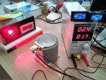
DTR tested Mitsu and Oclaro at max 1.7A and I also gave this current for 2, then 5 min. The ouput reading as you see was steady all time about 1.5W. As my old LPM has baseline at 0.16W under zero, we have to add it to the value and obtain 1.66W output at 2.4V/1.7A what means that this LD has ~40% efficiency. Me also do not know to chart curves, but later I will test this LD more precisely to know efficiency on output dependance.

RC and Alaskan mentioned before that this cooling setup produces moisture condensation. Yes, it does. But I did not notice any problem running it - hopefully the lens stays warm where the beam passes despite of cool mount body. And after 2nd min the T became steady at 10-13C, so a kind of equilibrium was established between heat producing LD and ice...

Also: foil T sensor from Lasertack was for sure faster responding (one on the left reader) and showing lower T than the 2nd sensor all the time.
 

Attachments

  • 22.jpg
    22.jpg
    85.5 KB · Views: 54
  • 33.jpg
    33.jpg
    71.4 KB · Views: 48
  • 44.jpg
    44.jpg
    93.1 KB · Views: 49
  • 55.jpg
    55.jpg
    77.9 KB · Views: 53
  • 66.jpg
    66.jpg
    90.6 KB · Views: 49
  • 77.jpg
    77.jpg
    45.2 KB · Views: 51
  • 88.jpg
    88.jpg
    87.4 KB · Views: 59
  • 11.jpg
    11.jpg
    79.2 KB · Views: 51
Last edited:
Really nice work.
I need to carve out some more time to experiment with optics so I can contribute something meaningful.

I just want to point out that the laser diode datasheets seem to specify the operating current according to the input current that results in the most efficient output. You may get higher efficiency between 1.3 and 1.7 Amps. Still, 40% is quite good.

If you need help with the plots, I can help with that. It's quite easy with a spreadsheet program like Microsoft Excel or Goolge Sheets.

Hi CDBEAM and RA,

So, generally the divergence through G-2 as mentioned before looks like that of NUBM44.

DTR tested Mitsu and Oclaro at max 1.7A and I also gave this current for 2, then 5 min. The ouput reading as you see was steady all time about 1.5W. As my old LPM has baseline at 0.16W under zero, we have to add it to the value and obtain 1.66W output at 2.4V/1.7A what means that this LD has ~40% efficiency. Me also do not know to chart curves, but later I will test this LD more precisely to know efficiency on output dependance.

RC and Alaskan mentioned before that this cooling setup produces moisture condensation. Yes, it does. But I did not notice any problem running it - hopefully the lens stays warm where the beam passes despite of cool mount body. And after 2nd min the T became steady at 10-13C, so a kind of equilibrium was established between heat producing LD and ice...

Also: foil T sensor from Lasertack was for sure faster responding (one on the left reader) and showing lower T than the 2nd sensor all the time.
 
Hi logsquared,

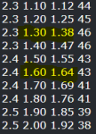
You wanted to know OP vs current graph. Here I have tested the (corrected) output vs voltage/current. Here is the table.

RA, please do curve if you know how to. Do not pay attention to last zeros of any number - I just put them for formatting reasons. Also calculated efficiency for each reasonable I value.

V A W efficiency (%)
1.9 0.10 -
2.0 0.20 0.04
2.0 0.30 0.11
2.1 0.40 0.34
2.1 0.50 0.43
2.1 0.60 0.55
2.2 0.70 0.64
2.2 0.80 0.69
2.2 0.90 0.90
2.2 1.00 1.00
2.3 1.10 1.12 44
2.3 1.20 1.25 45
2.3 1.30 1.38 46
2.3 1.40 1.47 46
2.4 1.50 1.55 43
2.4 1.60 1.64 43
2.4 1.70 1.69 41
2.4 1.80 1.76 41
2.5 1.90 1.85 39
2.5 2.00 1.92 38
let cool down to 2ºC
2.5 2.10 2.06 39
2.6 2.20 2.08 36
2.6 2.30 2.09 35
2.6 2.40 2.11 34
2.6 2.50 2.12 33
let cool down to 2ºC
2.6 2.60 2.32 36
2.6 2.70 2.18 31
2.6 2.80 2.13 29
2.7 2.90 2.09 27
2.7 3.00 2.03 25


left 2 min at 2.5A
let cool to 2ºC
left 5 min at 2.5A
Every time measured steady output of 2+W.

You can see that there was jump in power each time after cooling down to 2ºC - so the output at 2.5A could be 2.3W if LD would be kept that cool, but when T rises to equilibrium at 10-14ºC the output drops to ~2.05W.

Here are more pictures - remember that zero line is at -0.17W with this LPM!
 

Attachments

  • bb.jpg
    bb.jpg
    79.5 KB · Views: 22
  • ee.jpg
    ee.jpg
    88.9 KB · Views: 33
  • dd.jpg
    dd.jpg
    91.9 KB · Views: 26
  • cc.jpg
    cc.jpg
    81 KB · Views: 22
  • aa.jpg
    aa.jpg
    89.2 KB · Views: 22
  • 99.jpg
    99.jpg
    80.4 KB · Views: 25
I'm interested in this diode.. what ratio of C lenses were used in testing (3X, 6X, etc.)? If 3X was used I am curious as to how a 6X cylinder pair would work out.

This is something to consider if running this diode above 1.3A, if Ushio's datasheet (@ https://www.ushio-optosemi.com/documents/uos/products/UOSE_DS_HL63283HD_R2.pdf ) is accurate-

attachment.php


attachment.php


attachment.php
 

Attachments

  • Ushio Wavelength Brightness.PNG
    Ushio Wavelength Brightness.PNG
    17.2 KB · Views: 248
  • Ushio datasheet.PNG
    Ushio datasheet.PNG
    75.2 KB · Views: 249
  • Ushio test.PNG
    Ushio test.PNG
    5.8 KB · Views: 245
I got a cyl lenses trio from Techhood that covers this wavelength. It is rated to expand 3X, though. I won them in an auction for ~$20.00, IIRC.
 
Hmmm...This diode...along with the G71, P73, 63193....all Multi Reds....all require the 2mm EFL lens from LSP for collimation....and are corrected best....with 6X C-lenses.

Expect aberration / ghost wing's above and below the Far Field main beam geometry....which can be masked to a certain extent.

IMNSHO.....the 63193 still delivers the best higher power with the least amount of artifacts.


Yes....cooling does really kick up the output on this diode....but...it also does so for the list of high power reds above.

We have already seen some active cooling arrangements applied to a Hand Held . They work....but...alas...are quite bulky.

That said....I suppose....for a HH Red.....I would employ a dual 63193......might use a knife edge arrangement to result in a more rectangular output when beam atop beam are stacked ??? I do not think that has done yet....sigh....just add it to the list :undecided::undecided::undecided:

CDBEAM


I'm interested in this diode.. what ratio of C lenses were used in testing (3X, 6X, etc.)? If 3X was used I am curious as to how a 6X cylinder pair would work out.

This is something to consider if running this diode above 1.3A, if Ushio's datasheet (@ https://www.ushio-optosemi.com/documents/uos/products/UOSE_DS_HL63283HD_R2.pdf ) is accurate-

attachment.php


attachment.php


attachment.php
 
Last edited:
Yes, Bob, deadshadow has reached almost 1.5W peak from TEC-cooled P73 here but its LD might have been at 0ºC for that moment?
https://laserpointerforums.com/f50/my-handheld-tec-cooled-ml501p73-almost-finished-101861.html

We know that P73 has less divergence than Ushio but its low price makes it easy to replace only in single LD builds. However, when I wanted to replace one LD in a big combined setup, then it took a lot of work readjusting the mount, mirrors etc. You know...
The question is which of these 2 LDs is more robust to produce these 1.5W when cooled let's say to 10-15º and not under 0º?

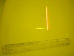
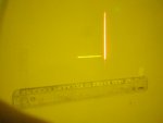
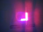
And to finish the study wih Ushio I checked its divergence with G-2 compared to NUBM44 at 5m - as expected it is almost 2x higher but only from WL 40% higher it should have 40% more divergence even at same emitter size I suppose. Sorry for lines not being parallel but this is how LDs are installed in my builds, I was to lazy to rotate...and how can I rotate the ice bath keeping ice inside???
On pics NUBM44 was set at 1.6A, Ushio at 1.6, then 2.5A but on 2nd pic the red line does not look brighter, maybe aaron is right that more power but higher WL results in same perceived brightness. So no need to go over 1.3A...
Both good shots were made through 2 googles put one after another.

Here Podo has comparison of this LD (called Hitachi) with other reds:
https://laserpointerforums.com/f50/new-1-2w-638-diode-check-out-98855-2.html
 

Attachments

  • 44+Ushio 1.6A.jpg
    44+Ushio 1.6A.jpg
    80.9 KB · Views: 35
  • 44+Ushio 2.5A.jpg
    44+Ushio 2.5A.jpg
    79.1 KB · Views: 38
  • 44+Ushio 2.5A no goggles.jpg
    44+Ushio 2.5A no goggles.jpg
    97.9 KB · Views: 38
Yes, Bob, deadshadow has reached almost 1.5W peak from TEC-cooled P73 here but its LD might have been at 0ºC for that moment?
https://laserpointerforums.com/f50/my-handheld-tec-cooled-ml501p73-almost-finished-101861.html

We know that P73 has less divergence than Ushio but its low price makes it easy to replace only in single LD builds. However, when I wanted to replace one LD in a big combined setup, then it took a lot of work readjusting the mount, mirrors etc. You know...
The question is which of these 2 LDs is more robust to produce these 1.5W when cooled let's say to 10-15º and not under 0º?

And to finish the study wih Ushio I checked its divergence with G-2 compared to NUBM44 at 5m - as expected it is almost 2x higher but only from WL 40% higher it should have 40% more divergence even at same emitter size I suppose. Sorry for lines not being parallel but this is how LDs are installed in my builds, I was to lazy to rotate...and how can I rotate the ice bath keeping ice inside???
On pics NUBM44 was set at 1.6A, Ushio at 1.6, then 2.5A but on 2nd pic the red line does not look brighter, maybe aaron is right that more power but higher WL results in same perceived brightness. So no need to go over 1.3A...
Both good shots were made through 2 googles put one after another.

Here Podo has comparison of this LD (called Hitachi) with other reds:
https://laserpointerforums.com/f50/new-1-2w-638-diode-check-out-98855-2.html

to get 1.5w safely out of a single diode you definitely have to get the hl63282 as its more capable for higher power, the p73 is only rated 500mw for cw output and we already pushing it hard to over 1w,in best case you can get 1.3w out of it by feeding it 1.3A and no more,it is still too risky but this diode became cheap so its worth a try if you want a higher output.

my tec cooled build is still alive and running at 1.1A if i remember correct, although i changed the lens to 3 element for better divergence and trade of with power.
 
I know about it. The point is too long. Red High output is good however the divergence is bad
 
Vladimir....Just ran across this thread...must have missed it back in 8/2018 !!
THANX for the data for a chilled Hl63282 !!!!!!!!!!!! Interesting !!

I did some additional trials with this LD...while doing further work on the Chartreuse Coruscation !! I had some issues with too many artifacts !! ...perhaps my set up was not quite right !!!

Surly....2.13W out the front is the best to date for performance. Ice is nice....but.....a TEC would be much less problematic !!
But then....a TEC has its problems !!!

Currently....my single Hl63282 is installed in a Lumia Experiment I am working on !!…In this application....hmmmm....artifacts are of NO concern !!

Really....ALL the Multimode need 6X correction....this one included... The NDG7475. the N465.....and this Red LD. !!

However....With correction....comes a small amount of artifacts.......Asymmetry is greatly reduced....but we get some slight wings !!

Anyway....just my thoughts !! Thanx to all for your input !!!

CDBEAM
 
I found the NDG7475 to be far less divergent than the multi-mode 635-638nm diodes. It is just a bit more divergent than the NDB7875. I would think the cyl lens correction for these diodes would need to be less aggressive than the NUBM44s and the ML501P73s. I am still planning on a 638nm cyl lens corrected build. I have most of what I need to accomplish it.
 
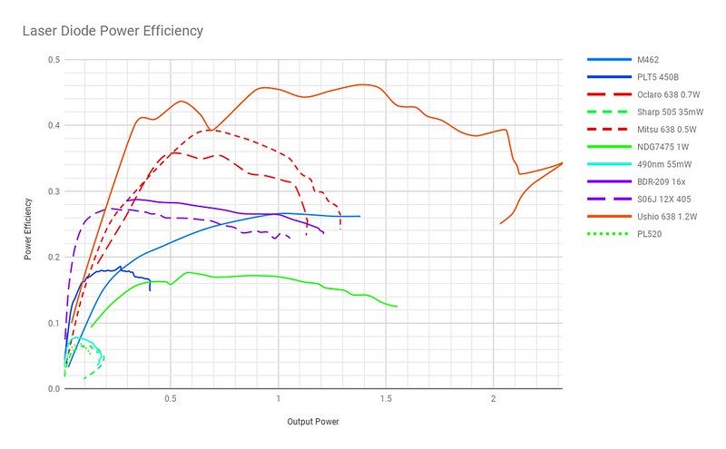
While this thread is still getting attention, I thought it may be interesting to some to see some information on efficiency.
This 1.2 W 638 is by far the most efficient diode available to us, approaching 50%.
In this first plot, you can see a comparison of many common laser diodes.
This plot shows how efficient (power out / power in) each laser diode is, by power output (x-axis). The y-axis represents the proportion of power output that is laser light. Why I prefer this metric is explained in this thread here: https://laserpointerforums.com/threads/a-tale-of-two-metrics.101542/
You'll notice that the peak efficiency for each diode corresponds with the manufacturer's CW operation specification. That's not a coincidence.

31851870727_0405725441_c.jpg


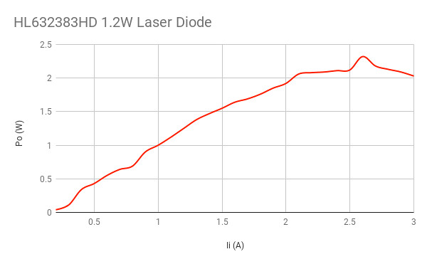
The second plot shows the more common measure of current efficiency (power out / current in).

46793550371_f8d240173d_z.jpg


Back
Top