Welcome to Laser Pointer Forums - discuss green laser pointers, blue laser pointers, and all types of lasers

Buy Site Supporter Role (remove some ads) | LPF Donations

Links below open in new window

FrozenGate by Avery

Micro stepper motors from bluray sleds

Joined
Oct 27, 2008
Messages
169
Points
0
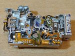
All bluray sleds these days have a small micro stepper motor that uses a screw drive to move a lens assembly. You can see it in the lower left corner on this 12x sled.

The motor appears to be a bipolar stepper motor (thats why they have 4 leads) and likely works similarly to the larger stepper motors that move the actual sled inside the bluray drive.

I am wondering if anyone here has tried to do anything with these motors for a spiro or some sort of micro scanner. The motors are pretty small but seem to at least be designed to make very small, accurate, and fast steps.

I have two 6x sleds on the way to the house and i plan to disassemble them with careful attention paid to the motor and its circuitry. My hope is that the existing circuitry may be used to compactly control this motor, we'll see.
 

Attachments

  • Plextor%2012x%20Sled.JPG
    Plextor%2012x%20Sled.JPG
    149.6 KB · Views: 3,106


Very good find.
I do not think any one has tried to use that motor for anything.
You would need to build a driver i do not think the circuit in the sled will be useful.
 
You can Google stepper motor driver circuits... A stepper works on the
same principles whether it is large or Micro...
You just need to check for the proper Voltage to use...

Jerry
 
Very good find.
I do not think any one has tried to use that motor for anything.
You would need to build a driver i do not think the circuit in the sled will be useful.

Oh contraire mes amis!

I have had a look at these tiny motors. Not a huge look but from my playing I think they can indeed be used. Not a huge current draw IIRC and 3V seemed to get it to step. They are dual pole but the step is larger than one would want for anything deadly accurate IMHO. (No degrees to offer here so just intuition). However, I think they would be driven from a PWM 555 timer circuit but not to any particular degree. The biggest issue I thought of is how to remove the worm gear safely! Much brutality and I fear failure, and I think they won't become really useful until that has been achieved.

The sensor on the side of the motor housing that's attached to the same PCB intrigued me as well. It looks like a tiny IR/photodiode setup to detect when a vain, and therefore the lens carriage, reaches end point. I initially thought hall effect sensor but I think not as the vain is plastic.

I'm pleased someone else has spotted these. I thought I was mad as no-one else has mentioned them so left it on the back burner. You may have inspired me to relook at this, many thanks. If anything is to report, then there is now a post. Well done!

M
:)
 
Last edited:
The worm gear on the 6x/4x motors are a lot smaller. I was planning on leaving it as is and mounting any optics/mirrors directly to the shaft.
Here is what the 4x motor looks like, note that taking off the ribbon probably destroyed the leads. I have 2 of these motors at home with broken leads because i pulled the ribbon off of them carelessly.
18804-how-extract-diode-optics-4x-gbw-h10n-all_module_parts_027.jpg
 
Yes, these are the motors I have looked at and they are well glued in! I broke the first carriage getting it out!

The reason i would want to remove the worm gear as a whole is simply the inertia. Not a lot I know but at such a small scale all the extra weight will slow response and I'm not sure these little guys have, 'all that', in terms of torque. For experimenting though this is of course not so important.

I think the resistance of the coils turned out to be something around 120 ohms, (seemed a lot to me so maybe you can confirm?), which gives an idea of what to try and run them at but without number of coils, magnetic flux, etc, then it's pretty much guess work as to how to run them properly. Finding a part number may help here but I couldn't. I went with the assumption that 5V may be max as we know the BR diode is being fed that but 3V got a step out of them.

I agree that pulling the ribbon off will not be healthy for these but I would solder at the point the ribbon meets the motor. Two are shared earth and two are for the poles for the coils but you porbably know that already. I look forward to further work on these. Certainly no-one's posted any other info so... New ground?!

Maybe DMX would be a good way to go for a control system? It's pretty tried and tested for stepper motor control re simple scanners. Just need to shrink it!

Keep us posted on this please. I'll dig mine back out at the weekend and add here if appropriate.

M
:)
 
i just finished taking the motors out of my two new sleds last night. Plastic housing on one was destroyed and the ribbon cable was already cut. On the other i have the housing intact and the ribbon is solid all the way to the sled board. I'll see if any tests on the board provides for easy control of the steps and i'll also work on some driver circuits this weekend if i have time. I have a white build that i've been working on lately that is distracting me from some of this, but i'll make updates on what i find.
 
I did a deconstruction of one of these today. I had been thinking about how they could be stepper motors as I suddenly had my doubts but the insides are confusing me...

2ibmb2u.jpg


All parts are laid out in the same place as the complete motor but aren't the coils in the wrong orientation for normal brushless motors?

The only thing I can think is that the small cage in between the coils become the electromagnetic poles. There are star shaped splines that extend inside the coils and the top set are offset slightly from the bottom. If current was passed, say through the top coil, and then the bottom coil then there might be a stepping type action but I couldn't find anything on the net that described this layout. Does anyone know what type of motor this is so I can do a search?

I'll get a better pic of the cage tomorrow as I have since straightened it back to correct shape but any clues would be great. In the pic above the splines look folded towards the centre but in fact stick up like a crown and act as a mount that the coils sit over before being sealed in the case. You can just see the ones on the other side as these are non-mangled.

[Edit: New picture of the straightened cage type arrangement]

sqtfys.jpg


I also counted the number of turns on the 4.5mm Diameter coils as 160 with a resistance of 21 ohms, (much less than the 120 or so I remembered in a previous post). The rotor is a permanent magnet that seems to have the poles split along its length? Difficult to be sure on that although it would make sense. The worm gear is actually cut into the spindle so is not removable.

Thanks,

M
:)
 
Last edited:
I did a deconstruction of one of these today.

Uhm, is just me, or this look more "mangled" than "deconstructed" ? ..... :crackup:


All parts are laid out in the same place as the complete motor but aren't the coils in the wrong orientation for normal brushless motors?

The only thing I can think is that the small cage in between the coils become the electromagnetic poles. There are star shaped splines that extend inside the coils and the top set are offset slightly from the bottom. If current was passed, say through the top coil, and then the bottom coil then there might be a stepping type action but I couldn't find anything on the net that described this layout. Does anyone know what type of motor this is so I can do a search?

No, this is a common constructive system for actual stepper motors, there's nothing wrong.

The inside magnet have "vertical strips" poles, means, the cylinder have the poles on the external side, alternated in vertical strips ..... the two coils are placed in that sense, and changes the magnetic polarity of the "spikes" of the crown, when you change the polarity of the voltage ..... as you see, they are not aligned, one is turned 1/4 of space respect the other, so the magnetic lines of the rotor become attracted or rejected from these changes, and this decide the sense in which you make it turn.

This type of motors are mainly used where you need more speed than force, opposite to the ones with magnetic discs or direct coupling poles, that are more efficent in strenght, but a bit less quick.
 
Uhm, is just me, or this look more "mangled" than "deconstructed" ? ..... :crackup:

QUOTE]


I'm hurt HIMNL9! :crackup:

Unfortunately these are spot welded in a sealed unit so mangling was the only way. I used the last of the dynamite to get in! Do you think I can get it working again if I'm really careful? I don't think they are any, "User Serviceable Parts", in these things!

No, this is a common constructive system for actual stepper motors, there's nothing wrong.

The inside magnet have "vertical strips" poles, means, the cylinder have the poles on the external side, alternated in vertical strips ..... the two coils are placed in that sense, and changes the magnetic polarity of the "spikes" of the crown, when you change the polarity of the voltage ..... as you see, they are not aligned, one is turned 1/4 of space respect the other, so the magnetic lines of the rotor become attracted or rejected from these changes, and this decide the sense in which you make it turn.

This type of motors are mainly used where you need more speed than force, opposite to the ones with magnetic discs or direct coupling poles, that are more efficent in strenght, but a bit less quick.

That's all great info, thanks! Last night I think I found some more info in a book, (Yes a BOOK! Analogue is great sometimes!), and I think these are, "2-phase, bipolar supply", motors and what you say about changing the polarity of the voltage fits right in line with that. Energising phase A+, B-, A-, B+, A+, etc for one direction and conversely for the other.

I might be wrong, (85% sure I am), but I wondered if the spikes were that shape to concentrate the magnetic flux density to either the base or the tip of the spike. Am I wrong in thinking that or is that just a quirk of construction? (I'm betting on quirk)

There are 5 spikes to each side of the crown, (so 10 per coil), does this mean, assuming no half-steps etc, that there will be 10 x 4steps to a rotation? (if the offset is a 1/4 turn...)

Experiment will show I guess but if I at least have a framework in my head then I may be a half-step forward!

Thanks,

M
:)
 
Last edited:
That's all great info, thanks! Last night I think I found some more info in a book, (Yes a BOOK! Analogue is great sometimes!), and I think these are, "2-phase, bipolar supply", motors and what you say about changing the polarity of the voltage fits right in line with that. Energising phase A+, B-, A-, B+, A+, etc for one direction and conversely for the other.

I might be wrong, (85% sure I am), but I wondered if the spikes were that shape to concentrate the magnetic flux density to either the base or the tip of the spike. Am I wrong in thinking that or is that just a quirk of construction? (I'm betting on quirk)

There are 5 spikes to each side of the crown, (so 10 per coil), does this mean, assuming no half-steps etc, that there will be 10 x 4steps to a rotation? (if the offset is a 1/4 turn...)

Experiment will show I guess but if I at least have a framework in my head then I may be a half-step forward!

Thanks,
M
:)

there must be also other 2 "crowns" from the sides, cause is this way that these motors works ..... and the number of the steps depend from the interaction from the number of the spikes and the number of the "strip poles" on the rotor ..... and from the fact that you drive it half-step or full-step, ofcourse .....

Need to go now, but this morning i will try to draw something for simplify the explanation.
 
Thanks HIMNL9. I think I have some handle on the operation and there are two corresponding crowns that interlace the central one and these form part of the case. You can just see one of these crowns in the base of the torn casing. Any drawings from you will help though, (I have seen some of your other explanations and look forward to more!)

It was difficult to determine the number of strip poles on the rotor but for simple construction I would suggest only two but this may not be enough to work. When holding the rotor laterally to the north end of a permanent magnet one side of the rotor was attracted. Holding the rotor steady and changing the pole to the south end, the rotor appeared to turn 180 degrees. Being so small though there may well be more.

Interesting stuff this...

M
:)
 
Ok, then, i will try :p

First, the "spikes " have this shape simply cause, for an automated machine, is more easy to produce parts with that shape, than with rectangular shapes, in small pieces ..... the same types of motors, when produced in bigger sizes, like the ones in printers, usually have these poles cutted in rectangular shape ..... as a secondary effect, this shape give to the movement from one step to the other a little bit more "smothness" (if i can say so), but this also produces less force.

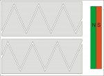
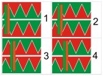
Now, in the draws i "unrolled" the polar crown in plane, cause i don't have 3D software here, and cause this way is more easy to explain (i also simplified it a bit) ..... basically, the coils give magnetic polarities to the crowns, depending from the polarity of the voltage, or no polarity at all if unfeeded (this for half-step operation only) ..... also, the 2 sets of poles are shifted of 1/4 of the space of a pole, for permit you to decide the rotation sense based to the switching sequence ..... so i drawed them in different colors for the various cycles, and also, drawed only one of the couples of the magnetic strips of the rotor, for the simplicity.

attachment.php


Considering N (north), the green color and S (south) the red color, , and remembering that same poles get rejected, and opposite poles get attracted, the ones in the draws are the sequences from full-step and half-step operations ..... in the full-step operation, the shifting is always from pole to pole, and the steps are ofcourse more large, and both the coils are always powered, so also the strenght is a bit more, where instead in the half-step operation the cycle is composed from 8 steps, 4 with both the coils powered and 4 with only one coil powered ..... this double the number of the steps and the resolution, lowering the force in the one-coil-only positions, cause in these positions the magnetic strips of the rotor are not aligned with full poles, but "balanced" between two of them.

I just hope that the draws can be understood :p :D

attachment.php


attachment.php
 

Attachments

  • 01.jpg
    01.jpg
    71.8 KB · Views: 1,947
  • fullstep.jpg
    fullstep.jpg
    190.9 KB · Views: 2,006
  • halfstep.jpg
    halfstep.jpg
    152.8 KB · Views: 1,869
Top drawings! That is perfectly understandable and more than enough to get going, (are the drawings based on christmas card designs? :p. That colour scheme is really festive!)

From the diagrams it may look like more steps are possible than I first thought. Experiment stage next then.

Great explanation. I'm sure that'll help more people than just myself.

+1

M
:)
 
Last edited:


Back
Top