Welcome to Laser Pointer Forums - discuss green laser pointers, blue laser pointers, and all types of lasers

Buy Site Supporter Role (remove some ads) | LPF Donations

Links below open in new window

FrozenGate by Avery

Lm317 - why???

Bucking circuits need specially designed PCBs to function efficiently and components like inductors, etc. that many people aren't skilled enough to source and design for. The beauty of linear regulators is that it doesn't require anything special to make it work, nor really any tuning aside from setting a resistance between 1.25V. It's probably the best decent constant current circuit one can build as a first-timer.


^^^ That is more or less what I was trying to say.

The OP was complaining about efficiency and why people use it, well, you can achive your wanted efficiency and have a good driver like a buck, but however it is alot less hastle to build a linear driver based around some IC (like the LM317 again) then to mess with switch mode converters.

@rhd,

Not that I know off, even the most basic Ive seen (IC based, internally switched) still require a decent part count (referance/feedback, the inductor of a specific value, diodes, etc). they still pose many more variables then just how an LM317 is set up.
 
Last edited:
Most of my stuff is wall-powered, and power is cheap. I run a 445 from a 12V supply. 1W out for 12W in. I don't care since it only costs a ninth of a cent per hour to run.

If I was worried about efficiency, I would have thrown out my ion lasers years ago :beer:
 
Huh? argon laser?
don't you mean space heater that emits light? :p
 
Is there a "DDL circuit" of non-linear driver DIYing?

IE - a fairly simple small buck circuit DIY circuit that can be easily adapted to suit different diodes, etc?

Do you mean decent efficence step-down only ?

There's the AX2002 that don't work bad, til approx 1A ..... unfortunately here the distribution is exactly zero, but they can be found also on DX mounted as led drivers, if needed for make some tests.


EDIT: i've found the link back:

http://www.dealextreme.com/p/3-6v-9...rcuit-board-for-cree-and-ssc-leds-4-pack-3256

Those ones uses AX2002 and are buck only ..... they need some decent capacitors at the sides, anyway, for work good, but must not be too difficult ..... (if i only can remember where the hell i throwed the old PCB test prototypes i made times ago with them :p)
 
Last edited:
Do you mean decent efficence step-down only ?

I did :)

Well, at least, I think I did. My understanding of the difference between a BUCK driver (which = step-down?) and a LINEAR driver, is that:

- BUCK driver turns excess voltage into current, and is thus efficient
- LINEAR driver turns excess voltage into heat, which sucks because heat has cooties so our lasers don't like it

800mA is zzzzz for a 445 (though might be nice for a 405) - however, could two of these be parallel for 1600 mA effectively?
$6.97 - 3.6V~9V 800mA Regulated IC Circuit Board for Cree and SSC LEDs (4-pack) - Flashlight Parts and Tools

Really though, I was thinking of a DIY circuit. The complexity of the step-down circuits I've seen built (like that above) doesn't seem beyond me in terms of component count. Designing it from scratch though, would be way beyond someone like me (though I'm sure not everyone here). Is there really no basic "starting point" circuit that we could establish some rules/formulas for, to address different current demands?

I'm not expecting something as simply as the DDL circuit (that's a joy to work with), but surely we don't need PCB fab experience and electronics training to take that next leap to a buck/step-down circuit? (here's to hoping)
 
Well, those drivers can be easily DIY, cause the reduced amount of components, anyway ..... i'm not sure if you can parallel two of them "already-made", but the IC itself is rated for 2A absolute maximum ratings, on the datasheet, so i think it can be modified (changing the 0.27ohm sense resistor (or adding another in parallel, there's an empty space for this marked R5 on the PCB) ..... only remember to substitute the original schottky diode marked SSY14 with a higher current one, the one mounted originally can't hold more than 1A.

In my old tests i had tried them til 1400mA, using a different schottky diode, the IC was becoming hot, but not "burning hot" ..... my main problem was the coil, i had only the original one, and with high currents it was causing more ripple on the output (probably using a coil with a higher saturation current it may work better, but here find specific parts is not too easy :p)
 
I don't know my non-LD diodes very well. Would a 1N5401 work?
 
Do you mean in place of the schottky diode ? ..... no. sorry, it need to be a fast diode, and usually only schottky diodes are fast enough and with enough current capability at the same time, for those uses.

Just as indication, you can use any MBRD320T4, or SS32 / SS33 / SS34, or MBRS320, or SK34-7 / SK35-7 / SK36-7, or B330-13 / B340-13 / B350-13 / B360-13, or STPS340, or if you stay under 1500mA also SL22, that are only 2A max, but probably more common to find ..... or any other equivalent of any of these ones.
 
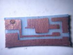
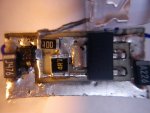
Here is my recent build driver for LOC Red diode running at 390mA
all is hand drawn and hand made

i used L1117

whacha think? :can:


P.S. the led on the finish pcb is for size reference only :D
P.S.S. the shape is actually a rectangular but my super macro lens makes it look like it's curved :D:D:D
 

Attachments

  • DSC00696.jpg
    DSC00696.jpg
    160 KB · Views: 83
  • DSC00697.jpg
    DSC00697.jpg
    194.2 KB · Views: 117
Last edited:


Back
Top