Welcome to Laser Pointer Forums - discuss green laser pointers, blue laser pointers, and all types of lasers

LPF Donation via Stripe | LPF Donation - Other Methods

Links below open in new window

ArcticMyst Security by Avery

LM1085 DIY Driver

jayrob

0
Joined
Sep 21, 2007
Messages
9,862
Points
113
I wanted to post a thread on this subject, because over that past couple of days, I have seen some posts that have said that there is no reason to use a FlexModP3 driver.

But there are some huge differences as discussed below...


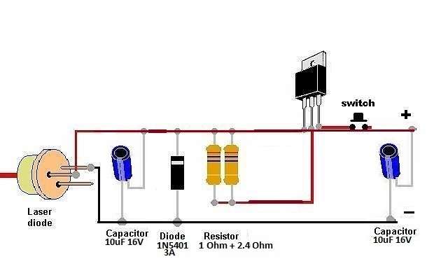
How to build your own 445 high output driver.

I edited this drawing with the information for 1.6 Amps, or 1.8 Amps:

Here's the LM1085:
http://parts.digikey.com/1/parts/614...t-12-nopb.html


445%20driver.jpg


The LM1085 has a low drop out voltage, but you will still need 3 X Li-Ion's with a blu-ray or a 445...

You can expect that the over all drop out voltage for the completed circuit will end up requiring 3 X Li-Ion's for your supply if using it for a blu-ray or a 445...

For a high ouptup 445 build, 2 X Li-Ion's will work at full charge, but the circuit will not keep in regulation for the capacity of your batteries. (as they drain, the set current will not stay in regulation with only 2 X Li-Ions)

Because the other components also have some voltage draw from the supply. Not just the 1085...

I think the silicon diode has a 1 volt drop out.

I hope I'm wrong, but I seriously doubt that we can match drlava's FlexModP3. (Only needing 1.5 volts above diode demand)

With a FlexModP3, you can use 2 X Li-Ion's in a 445 build, or even a 405 build, and up to 4 Amps output! (future proof)

Take a look at my Maglite kit... :D

The LM1085 circuit is still a great option to build for a 3 X Li-Ion set up. But if you want that kind of power using only 2 X Li-Ion's, like with a Maglite build, then you will have to go for the FlexModP3...


A couple of other things worth mentioning...

The heatsink on the FlexModP3, is some kind of non-conductive material. So that makes it easy to just heatsink it to the main sink...

But with an LM1085, it will most likely have a metalic heatsink, that must be isolated from the negative...

Also, you have a really nice pot to adjust current on a FlexModP3 driver. You get 100mA's per 1/2 turn.

See more information on the FlexModP3 here:
http://laserpointerforums.com/f42/flexmodp3-drop-module-rl-2088-frankenstein-host-61966.html

Just thought I would post this information to clear up a few things. And by all means, if I'm wrong about the needed supply, please do chime in and let everyone know how to build a circuit that can give a 445 build 2 Amps with only 2 X Li-Ions for the full capacity of the batteries! :)
 
Last edited:


rhd

0
Joined
Dec 7, 2010
Messages
8,475
Points
0
Hey Jayrob :)

I disagree with a bit of that - having played with the 1085 and 1084 a bunch lately.

"I think the silicon diode has a 1 volt drop out."
- It couldn't. There's no current flowing through it. It's a reverse polarity protection mechanism. You can actually leave it out if you want to.

"...end up requiring 3 X Li-Ion's for your supply if using it for a blu-ray or a 445..."
- Really strongly disagree. At full charge (2x ~4.1V) it's clear that only 2 cells are needed. But even at nominal battery voltage when not full charged (2x 3.6V), you've got 7.2V. Subtract the 5.2V that a 445 needs under high current, and you're still at ~2V remaining for the 1085. The 1085 circuit doesn't drop 2V. You're still safe. I think you'll have to dip below 3.2V per cell, before you start to notice anything.

"...and up to 4 Amps output! (future proof)"
- Maybe the 1085 tops out at 3A, but for basically the same price, from the same sources (digikey, mouser, etc) you can just grab the 1084, use it the same way, and you've got the ability to handle up to 5A.
 

jayrob

0
Joined
Sep 21, 2007
Messages
9,862
Points
113
Yes but have you built and tested a circuit with 2 X Li-Ion's and a 445?

I posted this after DTR built and tested a 1085 circuit with a 445 diode and a power supply. He found that the circuit shown in the drawing above, started to drop out of regulation at around 8 volts...

Just like any other LMXXX circuit that we have built in past times...
 

rhd

0
Joined
Dec 7, 2010
Messages
8,475
Points
0
I have - don't know what to tell you. I've even built a 2x 18650 test power supply based on the 1084.

I could see it dropping up to 2.25V in theory. My understanding is that ALL of the voltage exits the V-Out pin, and gets measured at the Adj pin. Since we need that 1.25V drop (it's what makes the whole equation work), I could understand that in theory the DDL circuit (regardless of IC) will never drop less than 1.25V.

What I don't know is whether the 1085 drops another 1V on top of the 1.25V, or whether it may drop 1.25V total.

Either way, at a max of 2.25V drop, for a 445 with a max Vf of 5.25 (I'm extrapolating this figure based on this, but would welcome a more precise figure), your batteries need to drop below 7.5V total before current starts to fall as a result of the diode's PIV curve.

Of course, if the resistor's drop is built into the the voltage drop figures we have for the IC, then there would be even more wiggle room.

At least - that's my understanding - and I could certainly be wrong.
 

jayrob

0
Joined
Sep 21, 2007
Messages
9,862
Points
113
I have - don't know what to tell you. I've even built a 2x 18650 test power supply based on the 1084.

I could see it dropping up to 2.25V in theory. My understanding is that ALL of the voltage exits the V-Out pin, and gets measured at the Adj pin. Since we need that 1.25V drop (it's what makes the whole equation work), I could understand that in theory the DDL circuit (regardless of IC) will never drop less than 1.25V.

What I don't know is whether the 1085 drops another 1V on top of the 1.25V, or whether it may drop 1.25V total.

Either way, at a max of 2.25V drop, for a 445 with a max Vf of 5.25 (I'm extrapolating this figure based on this, but would welcome a more precise figure), your batteries need to drop below 7.5V total before current starts to fall as a result of the diode's PIV curve.

Of course, if the resistor's drop is built into the the voltage drop figures we have for the IC, then there would be even more wiggle room.

At least - that's my understanding - and I could certainly be wrong.

3 volts is the bottom end of the discharge voltage... (not supposed to let them get less than 3 volts)

So for getting the full capacity out of a pair of Li-Ions, you will get to a little over 6 volts. Or maybe even 6 volts.

I'm talking about getting your full capacity out of the supply, You say you have tested, but have you got the regulated current out of your driver with say 6.4 volts supply, and a high current setting in a 445 build?
 
Last edited:

rhd

0
Joined
Dec 7, 2010
Messages
8,475
Points
0
3 volts is the bottom end of the discharge voltage... ...You say you have tested, but have you got the regulated current out of your driver with say 6.4 volts supply, and a high current setting in a 445 build?

No, admittedly I haven't - my use case for lasers doesn't demand that of my batteries between charging.

If you just compare the datasheets of the LM317 vs LM1085, there's a stated dropout voltage difference of about 1.3V at 1.5A.
 

jayrob

0
Joined
Sep 21, 2007
Messages
9,862
Points
113
Guess I might have to build one of these circuits and test it at 6.4 volts vs 8.4...


I trust DTR, who has tested his.

But I'm wondering if there is anybody else out there, who has also tested to see where the voltage is at, when this 1085 driver will begin dropping out of regulation with a high current 445 build...
 

DTR

0
Joined
Jun 24, 2010
Messages
5,684
Points
113
Let me start here. Jay I should have run a few extra tests because I have two drivers that I built that are identical in set up but I am getting two different results. The one I tested that I gave you a report on starts dropping current when it passes 8V. The second starts dropping @ 7.2V. I am at a loss to what the difference is.:thinking:

Either there is variations in these or my build may have something that I did wrong. I built them both exactly according to this diagram.

18adriver.jpg


With that said that means they start to drop when the batteries hit 3.6V which is far from their empty state. But it is still not as bad as 4V as initially reported. I have a third and I will build it tomorrow and see if what I get.


Here is a test I did a while ago with the P3 showing it did not start dropping until it passed 5.2V:D

 
Last edited:

jayrob

0
Joined
Sep 21, 2007
Messages
9,862
Points
113
Thanks for posting that excellent information...

That's exactly the kind of testing we need!

I tell you it's going to be hard to match that FlexModP3...

Plus the nice pot for easy adjustment, and the fact that you can heatsink it directly to the main sink. Where as the LM1085 must be isolated...
 

rhd

0
Joined
Dec 7, 2010
Messages
8,475
Points
0
Jib77 has done a bunch of work with this IC, he turned me on to it initially. It would be worth getting his input.

I still DO think that 1.25 is an absolute minimum dropout for any DDL-inspired design with an IC that has 1.25 as a vref.

Can I ask - do we have tested stats on the Vf for 445s at any current past 1200 from those old PIV curves?
 

DTR

0
Joined
Jun 24, 2010
Messages
5,684
Points
113
Here is a bench test I did a long time ago. Obviously it is not the most efficient diode we have come across and I am not sure if that would change the data any. This also raises a question for me in the video I posted above with the P3 it started to drop @ 5.2V but and according to this data the diode would have been close to 4.5V@1600mA. If the P3 requires 1.5V over that would be 6V.:thinking:

mA@V=mW

400@3.9=249
450@4.0=319
500@4.0=391
550@4.0=450
600@4.1=514
650@4.1=596
700@4.1=646
750@4.1=706
800@4.2=770
850@4.2=816
900@4.2=874
950@4.2=941
1000@4.2=996
1050@4.3=1046
1100@4.3=1077
1150@4.3=1163
1200@4.3=1219
1250@4.3=1268
1300@4.3=1306
1350@4.4=1367
1400@4.4=1434
1450@4.5=1494
1500@4.5=1550
1550@4.5=1597
1600@4.5=1630
1650@4.5=1652
1700@4.5=1670
1750@4.5=1692
1800@4.6=1710


Ok so if 3.0V is empty and you need a minimum of 3.6V with this driver would that not mean you can chop your batteries stated capacity in half when figuring runtims? Since the difference between 3.0V and 4.2V is 1.2V for full capacity and we are only using 0.6V? If this is right using 2800mAh 18650's you would get 1400mA to empty and drawing 1777mA give you about 42 minutes between recharging. As compared to a P3 that would give you 1 hour 26 minutes.
 
Last edited:

kozack

0
Joined
Feb 28, 2011
Messages
8
Points
3
This is exactly what I needed. I think lm1085 is an acceptable alternative to FM P3. I'll post my results as soon as the driver will be ready.
 

rhd

0
Joined
Dec 7, 2010
Messages
8,475
Points
0
Ok so if 3.0V is empty and you need a minimum of 3.6V with this driver would that not mean you can chop your batteries stated capacity in half when figuring runtims? Since the difference between 3.0V and 4.2V is 1.2V for full capacity and we are only using 0.6V? If this is right using 2800mAh 18650's you would get 1400mA to empty and drawing 1777mA give you about 42 minutes between recharging. As compared to a P3 that would give you 1 hour 26 minutes.

No - not at all. I see now why you guys were initially concerned about that last bit of battery drain! At first I couldn't understand why anyone would care about that last portion of battery juice ;)

See, li-ions voltage curve as it discharges isn't linear. That last ~3.6 down to 3 drops fairly rapidly. In this graphic below, picture our draw at just below the black line (a bit more than 1C) You're pretty much always above 3.6V until the last 5 or 10% of battery capacity.

li-discharge-curve.gif
 
Last edited:
Joined
Sep 12, 2007
Messages
9,399
Points
113
I think we should look more closely at buck LED drivers. They have the potential to be more efficient, smaller, and still cheaper than the flexmod.
 

anselm

0
Joined
Nov 22, 2010
Messages
2,448
Points
0
OK, I'm in the middle of doing a little test here.
My setup: LD1085 tuned with ~0.7Ohm for ~1.8A. 10nF ceramic caps on input and output.
Reverse protection diode.

I'm measuring battery voltage under load and diode voltage.
Pictures coming up.
Right now I decided take a short break to let the IC cool, the tiny heatsink is not enough.
 

jayrob

0
Joined
Sep 21, 2007
Messages
9,862
Points
113
Good deal...

If possible, better is to measure battery voltage under load, and current.

Since it's a linear driver, it's easy to measure current at the tail...


Top