Welcome to Laser Pointer Forums - discuss green laser pointers, blue laser pointers, and all types of lasers

LPF Donation via Stripe | LPF Donation - Other Methods

Links below open in new window

ArcticMyst Security by Avery

Knife-edging four NUBM44 in Lasertack micro module

Joined
Feb 12, 2016
Messages
589
Points
63
Hi Bob aka CDBEAM,

Sorry, many months I did not have much time for posting.
How is your project going?

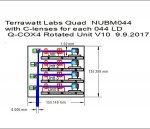
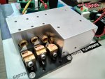
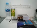
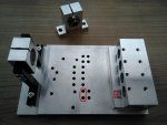
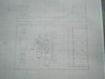
I made a new bigger baseplate somewhat similar to you drawing but for combining, not for KE.
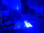
Here all 4 beams can be expanded before PBS, WP and dichro and also a Sanwu BE could be adjusted at the end (I hope hole positions are right).
As you can see the positioner was made from SK16 with hole expanded to 17.5mm (to accept Sanwu adapter) in L-brackets from Stanwax.
All was done by CNC shop here in Spain which jors has recommended to me. If it works we could start mass production one day...

Now they do another piece for KE, I will show it when ready.
 

Attachments

  • 1a.jpg
    1a.jpg
    60 KB · Views: 55
  • 2a.jpg
    2a.jpg
    75.8 KB · Views: 47
Last edited:


Joined
Sep 20, 2013
Messages
17,410
Points
113
Light superglue, looks promising. I'm looking forward to seeing if this works when you are done with it. + rep.
 
Joined
Feb 25, 2010
Messages
1,643
Points
113
Vlad.....Well....I did a Four (4) Banger @ Knife edging drawing...back in September....to show how I would do Knife edging to combine four (4) separate NUBM044 LD's !!! :eg:

I would machine parts.....for four (4) separate " Units " !!!!

LD /Collimation lens mount / Trio of Cylindricals....all mounted to an Ally base......That is a " Unit" !.....Then...

Rotate this entire unit...90 degree....as the concept drawing shows. ( See three bolts fixing the Units to the main base plate )

This arrangement would then deliver....Four (4) beams....Entering the Knife Edge units.... looking like this

l

So....in THIS orientation....the absolute minimum distance between individual beam geometries will be achieved..So..really close, like this

llll

We will be...fighting gravity....when adjusting the beam pitch....but standard issues with the Yaw !!! :undecided::(

SO....we could achieve great power density....and the combined beam geometry....I would predict to be 6mm x 6mm at the Near Field !! Maybe ....maybe .... 28W .....out the front door !!! :bowdown:...
And....with this C-Lens set-up....about 0.5 mRad !!! Hmmmm ??
I could be done...I am sure !!!

Yet ANOTHER project for 2018.....maybe 2019 !! :beer::beer:

Merry Christmas LPF....Another " Tin Foil " special 4 U !!!!!

Note: I'm work'in on finishing up Chris !!!!!! :eg::eg::eg:

:tinfoil::tinfoil::tinfoil:

CDBEAM
 

Attachments

  • 044-Q-COX4 Rotated V10.JPG
    044-Q-COX4 Rotated V10.JPG
    131.7 KB · Views: 47
Last edited:
Joined
Feb 12, 2016
Messages
589
Points
63
So, now let the saga about combining as much as possible power continue!

After almost 1 year I managed to make what several LPF members have suggested earlier - a new Quadro-HS mount for 4 DTR Cu modules with offset 4mm. In this way I can insert four NUBM44 inside while the beam geometry is
II
II

and not IIII as before. Would this allow to focus the beams at 5m better - let us see!

First - the 3 mirrors were adjusted on Lasertack micro baseplate to have this close range geometry (pic. 2).
What is to mention is that the 12.02 mm holes were too tight - rotation of modules inside was very difficult and the lines resulted not perfectly parallel at the end (pic.3). The holes should better be 12.05mm or more.

Second - it was mounted on the Al baseplate with cylindrical lenses on guides. Oh does not it look like a tank gun now?
The last pair of 6x cylindricals from Bob aka CDbeam were of exactly right heigt for this project. He is doing the GB for more of these pairs right now - this is good for all of us.

Bob, I hope you read this thread!

Third - burning tests! Over the tank gun you can see the mark on the white wall this thing made at 4A current just in 5sec from 5m distance.

Sorry, I did not do more burning tests after this thing in seconds I needed to take picture 5 made a hole in white 1mm thick PS sheet which I had expected to reflect the beam and almost burned through a black 3mm thickness PVC sheet behind it producing a lot of smoke...

I am in doubt - how should I protect the walls from such a POWER???
 

Attachments

  • KE1a.jpg
    KE1a.jpg
    545.1 KB · Views: 23
  • KE2a.jpg
    KE2a.jpg
    475.3 KB · Views: 22
  • KE3a.jpg
    KE3a.jpg
    556.9 KB · Views: 19
  • KE4a.jpg
    KE4a.jpg
    512 KB · Views: 21
  • KE5a.jpg
    KE5a.jpg
    294.6 KB · Views: 22
Joined
Jul 10, 2015
Messages
9,896
Points
113
Why not use 4x C lens pairs and knife edge in a row like the drawing llll ?
Then you could run the corrected and knife edged beam through a large beam expander.
 
Joined
Feb 12, 2016
Messages
589
Points
63
Well, this 4x C lens pairs, then KE design I better leave for combining 8 beams from NUBM08 block. Because there will be no chance to get a decent correction even at one focus points like above with a single pair.
What BE do you suggest at the end - it will need to have a really big apertures!

But for focusing 4 beams one pairs works pretty fine and simple - why to do it more complex?
And yes, I wanted to improve focus by positioning a 2nd pair of cyl 90º rotated or install a spheric BE at the end but with all optomecanicals for that the tank gun will no more be as compact as it is now.
 
Joined
Feb 25, 2010
Messages
1,643
Points
113
Vladimir....Impressive...Impressive indeed !!!!! ....Looks like a Tank Turret....and....Built like a Tank !!! MASSIVE.....great heat sink for those Heat generating 044's

Been thinking about a simple solution to your DTR module rotational problem !!!!

The goal...is to be able to rotate the modules....In Situ....as they are positioned within the Ally Block Heat sink !!
SO.....alignment must take place...as all 044 modules are turned on ( Perhaps at a 20~30% power level)….." Power-on" alignment !!

ONE way to accomplish would be to modify the Heat Sink Block and the CU Module case.

One could add four (4) alignment access bore holes....oh....say 8mm in diameter.....to the Ally Heat Sink. These access bore holes would be close ( Maybe 5mm) to the rear set/grub bolt holes....be parallel to the set/grub bolt holes....and provide access to the top of each module.

SO....Why the access holes ???? Well.....IF there were a small bore hole....say 1.5mm diameter....drilled in each CU module.....THEN.....a small diameter alignment tool could be inserted down into/thru the 8mm access bore....and " Power-on" alignment. could be accomplished via the alignment tool.

Hahaha....easy to type.....some challenge to accomplish....at THIS stage of the unit completion !!! A few suggestions....( Which arise from my past experience)

1) Mark the rotational position of each module.
2) Remove the CU modules....and mark which module came from which module bore ( 1,2,3 and 4) from bore ( A, B, C, D)
3) Remove the HS block from the main Base Plate.
4) Drill the our (4) 8mm Access bores. The access bore must be along the Module Centre line and should be about 5mm from the rear Grub/Set bolt hole
5) Reinsert all modules back into their respective holes.
6) Reattach the HS Block with modules.
7) Using the previously marked rotational position, realign your modules....back to the best beam-to-beam parallel state you can achieve.
8) Using the access bore, mark the centre point on each module. ( I use the drill bit I used to make the bore to mark the centre )
8) Now...a tricky part !!! Remove the modules....again.
9) Using the mark on each module.....Bore a 1.5mm hole into each CU module....CAREFULLY trying to NOT to enter the module hollow interior. We do NOT want to get the drill entangled with the Anode/Cathode LD wires !!!! ( Practically....if you DO bore thru the wall.....keep your entry into the module interior...at a MINIMUM !!)
10) Re-install your modules back into the HS block ( In the correct match... bore to module 1-4).
11) NOW...Rotational align each module in the " Power-on" state...by inserting the Alignment tool into the hole drilled into the CU module....while you have only partial clamping of the Grub/Set bolts engaged. Set the rotation for best Far Field parallel beam condition.
12) Clamp tight your eight (8) Grub/Set bolts.

Hmmmm I Think I got this right` !!! …...Just trying to help...and solve a problem !!!

Thank you for sharing !!!! Might I suggest a few beers or a tall glass of wine to calm your frustrations during the alignment process !!!
NO....NO Weed.....You will not have the Will Power to finish the job !!! Hahahahaha.

CDBEAM
 
Last edited:
Joined
Jul 10, 2015
Messages
9,896
Points
113
I may not understand your goal, are you trying to bundle the beams ?

Seems like the beams would be less likely to get skewed as llll, the beam expander you would need to make yourself as I don't know of one you could buy ready made with this size input. If set as llll all the lines diverge getting longer and wider keeping better geometry than the 2 by 2 which would be good for Gaussian beams.

I was also thinking about testing an 8mm FL aspheric primary before each c-lens pair rather than the 4mm FL aspheric G2 which should further reduce the divergence of the corrected beams, also I was thinking about using NDB7A75 diodes, but that's just a side thought.

Good luck and thanks for sharing the pics.
 
Last edited:
Joined
Feb 12, 2016
Messages
589
Points
63
Hi Bob,
You did a lot of typing! But the main problem here what I already mentioned is that holes were too tight being 12.02mm, if not I could have found means to rotate them to make more parallel. But even this "turret" burns - what else do we want?

So, first of all to make it perfect I will have to disassemble all thing, widen the holes and then do what you suggest and then realign all optics etc. for what I really do not have Will Power now any more.
But I will use your idea for the build acc. to pic. in pos 65 - to combine 2 NUBM44 + 2 N465 with B-B dichro. One day I will come back to this project. And the holes there are already 12.05mm - lesson learned from previous troubles!

Hi RC,
I am trying to focus non-corrected beams all at one focus point at a reasonable distance while using as little parts as possible.

The issue with iiii geometry in this kind of a setup I made previously was explained a year ago on the schetch to post 48 - because of aberration 2 external beams (1,4) focus closer than 2 internal beams (3,4) and I could not achieve high power density (burn the wall!) back then.
I have even tried to put Sanwu BE before cyl pair and other things... with promising results and also to mention is that last cylindrical had to be very wide in this case... and it was not a compact setup any more.
Aspheric cylindricals might solve the issue... maybe...but they are not common glassware and toooo expensive...


Top