Welcome to Laser Pointer Forums - discuss green laser pointers, blue laser pointers, and all types of lasers

LPF Donation via Stripe | LPF Donation - Other Methods

Links below open in new window

ArcticMyst Security by Avery

How to measure current!!!

Joined
Oct 11, 2008
Messages
134
Points
0
THIS IS How to measure current!!!

Hello everyone,
I have noticed that many people new to the hobby and even people new to building thier lasers don't know how to measure current draw with a DMM ( digital multi-meter).
So here is my attempt at a tutorial. If this is a success I hope it will be stickied.
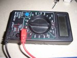
1. get a DMM as seen in the photo.
2. set the dial to "10A", it stands for 10 amps
3.plug the black cord of the DMM into "COM" and the red wire into "10ADC"

that is the DMM set up.

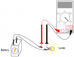
now the easiest way to measure the current on a laser is to take the tail cap OFF the measure from there. Current is always measured in series within the circuit as opposed to parallel. As seen in the diagram

ok now in this case the green laser is case positive so touch the red lead on the DMM to the battery + and the black lead to the case of the laser or the other positive where the battery would normally make contact with, thus completing the circuit.
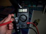
4. you should have your reading now.

Ex. my reading was0.36 which means 360ma
so there you go that is how to measure current.
 

Attachments

  • current graph.png
    current graph.png
    22.5 KB · Views: 17,700
  • 5mw green laser current measure resized.JPG
    5mw green laser current measure resized.JPG
    56.6 KB · Views: 2,050
  • DMM current setting resized.JPG
    DMM current setting resized.JPG
    90.7 KB · Views: 1,080
Last edited:


Joined
May 12, 2009
Messages
1,403
Points
0
This information is available in several places on the forum, but nice contribution. +rep
 
Joined
Nov 7, 2008
Messages
5,725
Points
0
Normally, they would be the same basic process, but you have to look at a dial instead of the numbers outright.

Also, the current reading method described above will yield the current draw of both the diode and the driver. In a purely linear driver, the two figures will be nearly identical since the drive circuitry itself uses only a tiny amount of current. If the driver has any boost capability or is non-linear (switching) the diode current can be considerably different than the overall current. We typically get around this by setting the current at the diode connections using a test load.
 
Joined
Mar 8, 2009
Messages
710
Points
0
Sure, why not?

Also it's a good idea to use the proper measuring range. For the DMM depicted in the first post, you'd use the 200mA range for measuring the ~120mA for a PHR bluray. Note that generally using the lower current ranges requires using a different plug on the DMM than for the 10A range - you can see this in the 3rd pic on the original post.
 

HIMNL9

0
Joined
May 26, 2009
Messages
5,318
Points
0
Only one precisation to always keep in mind: NEVER use this system for set the current of a driver.

ANY multimeter, regardless if digital or analog, read the current just putting a resistor in serie to the circuit, and then reading internally the voltage at the sides of this resistor (it's internal, ofcourse) ..... and when you measure the current that flow in the diode, you're measuring it through also the internal resistor of the multimeter, so when you detach it, the effective current increase, cause you have just took away the resistor that was in the serie circuit (the multimeter itself)

As far as i know, professional instruments are always trying to reduce this resistance, but it can never be turned to zero (and i personally don't feel to spend some hundred of euros just for have at home a 10 milliohm instrument :p :D), so always be careful with this, in presetting currents of drivers.

The better system, if you want to do a good work, can be to put a 1 ohm, 1 or 2 watt, 1% or better, in series with your diode, then put the multimeter in parallel to the resistor and read the voltage at the extremities of it, considering that with 1 ohm, each millivolt that you read is one milliampere that flow through the diode ..... this way, also, you know already the resistance (that is usually never indicated for the internal mA circuitry of the multimeter), so you can also calculate of what the current change when you take away the resistor, and preset the module keeping count of this value.


EDIT: just for give you a more clear idea about what i mean ..... considerate setting a red diode, as example, that shows 2,5V of working voltage, to 250 mA ..... this mean that at 250 mA, your diode acts as a resistor of 10 ohm ..... now, a cheap multimeter can also have an internal resistance of 10 ohm, on mA scale (don't think cheap DMM uses high speed, high noise rejection amplifiers ..... not when a chip cost usually as 3 or 4 DMM's, LOL) ..... this mean that if you set the driver at 250 mA, you're doing that on a circuit that is 20 ohm total ..... if the driver is not a circuit that self compensate (like LM317, as example), but is one of those common cheap voltage regulators drivers, when you take away the multimeter, you half the resistance of the circuit, that pass from 20 to 10 ohm ..... and this double the current, that pass from 250 to 500 mA ..... :D
 
Last edited:
Joined
Mar 8, 2009
Messages
710
Points
0
I disagree. The same current that flows through the internal resistor of the multimeter also flows through the diode. The only difference is that there will be a slight voltage drop, so the driver will have to produce a bit more output voltage as well. This is irrelevant, as keeping the current constant despite changing V requirements is exactly the purpose of the CC driver.

A DMM measures current by converting it to a voltage across a shunt (resistor). Actually a DMM measures only in one range, which is 0..200mV. Everything else gets converted to this range by selecting an appropriate voltage divider network (for V ranges) or shunt (for A ranges). Thus, in the 200mA range, the resistance would be 1 Ohm.

Also, an analog amperemeter does NOT convert the current to a voltage by using a resistor. For analog instruments it's exactly opposite, everything gets converted to a current, because these instruments measure the magnetic field generated by the current flowing through a solenoid.

HIMNL9s last example is incorrect because from the description it's clear that he's talking about a CV driver, which you don't use for driving diodes. (The LM317 is, by the way, a cheap voltage regulator driver. It's the feedback from the current sense resistor that turns it into a CC driver.)
 

HIMNL9

0
Joined
May 26, 2009
Messages
5,318
Points
0
^ Sorry, but if you read the post, you see that i stated already that the error is generated usually using drivers that don't have a self-regulation, like Cv drivers ..... in the current regulation configuration, the LM317 IS a self-regulated driver.

Also, please look at the usual schematic of amp meters, including analog ones ..... still a big, high current, low value resistor, with a microamperometer in parallel, that read the voltage at the sides of the resistor (there are not too much ways, for measure a current, after all :)) ..... the only exception are the professsional heat wire meters, where the measure is made using the dilatation of a known alloy wire, that change lenght proportionally to the current that flow through it and heat it .....

Not for criticize you, but i suppose i know how they works ..... after all, i'm using them only from 35 years ;)
 
Joined
Mar 8, 2009
Messages
710
Points
0
This "self-regulated" is not an actual technical term. Of course both CV and CC drivers are regulated, and they do it themselves.

The shunt in analog ammeters has the same purpose as in digital ones, it's a network to split the current: one part goes through the resistor, the other through the coil, in inverse relation to the resistances. That's how you select ranges. It has nothing to do with "reading voltages". Look up the "Kirchhoff rules".

If I may be blunt, using something doesn't imply understanding the theory.
 
Last edited:

HIMNL9

0
Joined
May 26, 2009
Messages
5,318
Points
0
Uhm, maybe i had to precise "using and building them" :p

Your example about analog meters is correct only til a certain point, and only for high currents, sorry.

If you have to measure 10A, you can also just use a coil EM meter ..... with 10 turns of 3 mm dia copper wire, the resistance is in the order of milliohm and don't interfer with the reading, but if you're precisely measuring milliamperes or microamperes, you just can't do it with a pure coil meter.

Having at home some analog instruments, i measured the internal resistance of some of them ..... the usual resistance for 1 mA instruments, as example, is 1 Kohm, and for a 100mA one is around 100 ohm ..... do you think you can add 1 kohm (or also just 100 ohm) to a circuit where you're measuring milliamperes, without influence both your reading AND the working parameters of the circuit ? ..... i really doubt about that .....

Your example about the network and Kirchhoff law is correct in theorical way, but at the practical act, you still measure differential voltage at the sides of the low value resistor with a high value, sensitive (and most of the times, amplified), voltmeter, when you use one of them (dismantle one and check, if you don't trust me ;)), cause over a certain range, your meter, with the correct shunt value for not influence the circuit that you are testing, just can't get enough current on the meter coil for move it :p ..... same as when you use, as example, an 0,1 ohm 0,5% constantane resistor for measure microamperes (the only practical and efficent way i found for not influence the circuit under test) , reading the voltage value at the sides through a 20.000 times, low noise, high speed, op amp chain ..... you can change the principle of the description, but not the substance of how the thing works, basically :)

I understand, and agree, that you're speaking about basical theories of electronics, but here i think we're more speaking about practical effects that these theories have, applied on practical laser circuits ..... and if you put a mA coil instrument in serie of a LD, you false your reading for sure, also cause usually peoples here uses CV cheap drivers, or at least 3-op-amp configuration circuits, that are built for a reduced range of resistance and voltage drop of the diode in working condition ..... i have some of them, around ..... the better one use 1 ohm resistor for current sense, the others from 2,7 to 4,7 ohm :p .....

Consider this ..... if, as in my previous example, the internal resistance of the diode in working condition is 10 ohm, and you add also only 100 ohm coil-type milliamperometer in serie, you increase the load resistance of 1000%, and as far as i know, there is no LD driver that can compensate this difference and remain stable, including PWM ones ..... the better linear LD drivers i tried, that uses a 4-op-amp configuration with an external power transistor, can barely compensate around 150% of variation in the load resistance, during working cycle (that for 10 ohm, means 15 ohm more, not surely 100 :))

Speaking, ofcourse, about LD drivers that can be buyed and used in modules ..... you can easily build a lab style module, powered with + and - 12V, that compensate so much, but i think you have some difficults fitting all the components in a LD module :)


BTW, "self-regulated" may not be a technical term, but is how, in the practical field, the thing works ;)
 
Joined
Mar 8, 2009
Messages
710
Points
0
Currents in the microampere range only flow in high-resistance environments, so in this case even a resistance of one kOhm would be insignificant.

You grossly overestimate the internal resistance of moving-coil instruments. Even the large types used in school (Phywe) drop .1V at full scale, meaning an internal resistance of 1 Ohm at 100mA. I've checked some other datasheets, the max voltage drop in the current measurement range is 0.1V for the uA ranges, and less for the higher ones. Either you've got really clunky instruments, or you're measuring them wrong (which is what I suspect).
 

HIMNL9

0
Joined
May 26, 2009
Messages
5,318
Points
0
Well, measuring them for DC application, i just put a DMM on the terminal of them (no reason for use an AC instrument, if i don't care about the inductance factor)

It's difficult to measure wrong a pure resistive value ..... at least, not when 3 of the 5 DMM's i have around give me the same values :)

And no, sorry, but microamperes values are not only in high resistance circuits (at least, not in some of the ones i made, LOL) ..... anyway, for LD's, we're talking about milliamperes in few ohm equivalent networks, so, also an 1 ohm instrument, can change your reading of 10% of the value (that is a lot) ..... and in some posts, i seen peoples that fried LD's just pushing them 10 mA more :)
 
Joined
Mar 8, 2009
Messages
710
Points
0
Having microamperes in non-high-resistance environments, let's say 1Ohm, means you're talking microvolts as well... and thus picowatts. You're not going to measure that with any instrument available to the public.

So, you're saying that using an ammeter with a 1 Ohm internal resistance will cause a big error... and instead propose using a 1 Ohm resistor and then measure the voltage drop over that? Now how sensible is that?

Besides, it seems you still don't know the purpose of a CONSTANT current driver. One that couldn't compensate for a variation in load resistance of 10% or less wouldn't be worth the name.
 

HIMNL9

0
Joined
May 26, 2009
Messages
5,318
Points
0
I never said i use only instruments available to the public ..... when i need something inusual, i build it myself (the example of the 20.000 times amplification chain was not theoric, is just a current probe i built for a similar measure times ago ;))

But i think we are going a bit offtopic, here ..... i just realized that we're passed from how to measure a current through an LD, to discussion about how to build non-commercial instruments, sorry for that.

About the suggestion to put an 1 ohm resistor (or if for that, 0.1 ohm, for loads that adsorb more than 500 mA, for me) in the LD circuit, is based on that what i usually do on all my lab style drivers, and means also that the resistor STILL STAY in the circuit for all the time of use ..... it's a different thing, compared to put and take away all the times an instrument in serie with the LD, you don't think ?

And, about "constant" current drivers, if you experiment long enough with discharge curves of cells, thermal drifts, load variations, and some funny avalanche effect rush of nonlinear loads, like LD's are in some conditions, you can discover that, at the end, some of these circuits will be a lot of things, but the first one is sure not "constant", LOL !
 
Joined
Mar 8, 2009
Messages
710
Points
0
Sure, the people designing these ICs sure don't know what they're doing...

I'm off.


Top