Welcome to Laser Pointer Forums - discuss green laser pointers, blue laser pointers, and all types of lasers

Buy Site Supporter Role (remove some ads) | LPF Donations

Links below open in new window

FrozenGate by Avery

Homemade Scanning Laser Color Projector/TV

Thank you for your help, but I have no clue how to find the torque constant, as it is the opposite of a motor. In addition it is not supposed to make a full rotation but only few degrees, so it's impossible to have a true constant angular velocity :(

For the laser feedback system I think I will use a photodiode array (maybe this one) with an Atmel or a PIC microcontroller.

Maybe I can try to build it and experimentally find with this feedback system a way to have something like a constant angular velocity (if the coil can produce a strong enough magnetic field it can overcome some non-linear factors and make the magnet have a constant angular velocity for a while). For example, if I take the angle vs time plot and I interpolate its function, I can find how the electromagnetic flux (and then the current into the electromagnet) has to behave in order to achieve a constant angular velocity.
It's a little tricky...
What do you think?


Thank you for your help, but I have no clue how to find the torque constant, as it is the opposite of a motor. In addition it is not supposed to make a full rotation but only few degrees, so it's impossible to have a true constant angular velocity :(

You don't need to know the angular velocity. Just try to measure the torque required to tilt the mirror one degree.
 
I realized that in the examples I made earlier even forces are nonlinear, so I think I'll return my path of the magnetic dipole. Yesterday I realized even that I can use directly a neodymium rigid support, in which B is supposed to be very linear and strong. I also thought about using the current carrying wire as the mirror hub. As I have to use a lightweight mirror (I think an acrylic one), I don't know if I can make more than one turn around the mirror, so I will probably need a lot of current, which I can obtain with a low voltage and a relatively large (14 AWG?) wire.
At this point, with a constant magnetic field, it becomes much more simple. Like a motor :D
Once I'll know the relationship angle vs time I will be able to digitally correct the laser modulation. Laser feedback concept can still be applied to find the mirror inclination.
 
I made another model, which uses the current carrying wire in a constant magnetic field principle. It uses 28 cubic N52 neodymium 10mm cubes to have a constant 0,5T magnetic field around the wires. In the model the two wires are formed by 50 turns of 24 AWG wire each, which will carry a maximum current of about 3A. Each side is capable of generating a 7,5N force under these conditions. A similar layout can work even with 20 magnets only, but with a force per wire of 5,2N. I think it's strong enough to let the mirror vibrate at the wanted frequency, maybe even an higher one. I hope there won't be problem of resonance...


Sketchup:
Download mirror.skp, upload your files and earn money.

It can work?
 
Because it can destroy the system :p

The mass of the mirror is inferior to 1 gram, the lever arms are 1 cm long each (total mirror length: 2cm), the force per arm is 7,5N.

Do you think it can reach such a high angular velocity?
Thanks


----------------------------------------------------------

EDIT: I give up, it seems too much difficult for my means...
I'll take from a broken DLP projector the DLP chip in order to use it with a RGV laser :D

Sorry if I couldn't find a solution not involving MEMS :(
 
Last edited:
Hello. I am back.
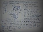
I'll explain some details of the KUNTMAN's scanner.

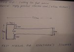
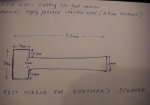
First step is to cut the fast mirror.
You can begin with a 5X50 mm rectangular bar of stainless steel.

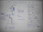
I will post a diagram for the driving circuit soon.

Good luck.
m.a.kuntman
 

Attachments

  • mir.jpg
    mir.jpg
    58.1 KB · Views: 2,382
Meanwhile there ist the Microvision SHOWWX Pico which would be easyer to buy and tune it with 1W Casioblue and the Rest.
 
Meanwhile there ist the Microvision SHOWWX Pico which would be easyer to buy and tune it with 1W Casioblue and the Rest.

Yes, dear Xer0; it is easear to buy a commercial scanner.
But the aim of this project is to explain how an amateur laserist can make his own scanner step by step without using any sophisticated pruduct.
It is a HOMEMADE SCANNING LASER COLOR PROJECTOR/TV as the title of this project says.

You have been asking the details for making this scanner for months.
Changed your mine?
Regards.
MAK
 
I'd really like to see a diode running at 5+MHz. Sure the diode can do it, but probably not the driving electronics.

I mean, 5+MHz AND it's modulating power... I dont know about that.

Even upon special request most laser manufacturers can only do up to 30kHz modulation... I've seen as high as 50kHz.

If it were using PWM modulation it would make a whole lot more sense to have such a super fast modulation rate, because that's how it works. But analog at a few mHz just doesn't sound right to me.

Hell yes they can. Take your average network switch SFP for example...
 
ppl have been asking you for months and you havent shown anything hence your rep. all you do is give bull shit teasers
 
The aim of this project is to explain how an amateur laserist can make his own scanner step by step without using any sophisticated product.

You will find below three figures showing main steps of making and driving the
fast mirror.


_________________________________
For some images pojected by this gadget
http://laserpointerforums.com/members/sltvm2007/albums/homemade-laser-scanner/
 

Attachments

  • mir.jpg
    mir.jpg
    58.1 KB · Views: 528
  • drv.JPG
    drv.JPG
    77.7 KB · Views: 1,185
  • scan.JPG
    scan.JPG
    92.8 KB · Views: 886
Last edited:


Back
Top