Welcome to Laser Pointer Forums - discuss green laser pointers, blue laser pointers, and all types of lasers

Buy Site Supporter Role (remove some ads) | LPF Donations

Links below open in new window

FrozenGate by Avery

High current bench power supply

djQUAN

0
Joined
May 27, 2013
Messages
1,154
Points
63
This is not laser related but I just wanted to share my latest project.

I needed a high current power supply when testing car amps so I looked around for options. Bench supplies more than 10A are very expensive. I saw the RC guys use this Dell server power supplies for their hobby chargers so I got myself one and tweaked it for my purposes.

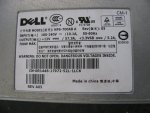
This is the powersupply nameplate
attachment.php


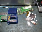
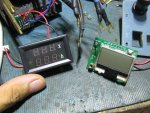
I needed a voltage and current meter but didn't have spare displays. I found I had the cheap hobbyking wattmeter so I tore it apart and used the board and LCD display. I also tore apart a broken cheap MP3 player and used the LCD backlight so that I can have a backlit display for the meter
attachment.php


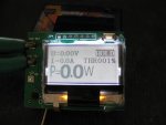
It worked :)
attachment.php


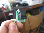
I needed to make a plug to connect to the control pins of the server PSU. I used two row female pin headers and perfboard for that.
attachment.php


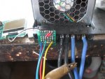
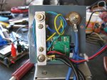
Here it is plugged in. I also soldered in 12ga silicone wire for the high current PSU output.
attachment.php


Instead of using the original 6" lenght of wire as the current shunt, I made my own using stainless steel plate which has a lower tempco compared to copper.
attachment.php


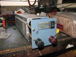
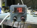
Here's the completed powersupply
attachment.php


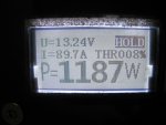
This is the most power I was able to pull through it after some tweaks. But the tweaks kept on tripping the internal protection so I turned it down after taking this pic.
attachment.php


It can do short bursts well beyond the nameplate rating. I could have cranked the voltage up a bit more but the overvoltage protection kept tripping so I settled on a 13.55V unloaded output voltage.

if interested, more details of the build can be found here:
High current bench supply
 

Attachments

  • IMG_1890.JPG
    IMG_1890.JPG
    150.7 KB · Views: 694
  • IMG_1891.jpg
    IMG_1891.jpg
    39.6 KB · Views: 766
  • IMG_1897.JPG
    IMG_1897.JPG
    76.6 KB · Views: 778
  • IMG_1896.jpg
    IMG_1896.jpg
    58.2 KB · Views: 1,011
  • IMG_2216.jpg
    IMG_2216.jpg
    60.2 KB · Views: 752
  • IMG_2220.jpg
    IMG_2220.jpg
    142.3 KB · Views: 783
  • IMG_2307.jpg
    IMG_2307.jpg
    112 KB · Views: 689
  • IMG_2221.jpg
    IMG_2221.jpg
    143.6 KB · Views: 1,545


Thanks guys. I wanted to have an output voltage of 13.8V or even 14+V but beyond about 13.6V the PSU kept on going into protect so I had to settle with 13.55V.

I believe it was rated at only 700W but was surprised when I was able to pull over 1kW from it. It got pretty hot though :D but it didn't blow up.
 
im sure theres a way to disable that protection circuit...althought its probably there for a reason :p
 
How do you accomplish the variable constant current regulation? I assume it is constant current?
 
How do you accomplish the variable constant current regulation? I assume it is constant current?

I though server PSUs are constant voltage with voltage sensing at the load to compensate for drop over the supply lines ,
 
Last edited:
How do you accomplish the variable constant current regulation?

There's no current limit in these, to the best of my knowledge. They just shut down if the current gets too high. Besides, car amps will get pissed if you try to operate them in constant current.
 
Yes, this operates in constant voltage output. It doesn't have a sense line so there's no way to compensate for the line drop.

If there's an overcurrent condition, it shuts down. When the voltage goes above or below an operating window, it shuts down. You'd have to cycle the power switch for it to turn on again. If the problem is still there, it shuts down again.

During bench testing, I connected a headlight lamp as a load (with high and low beams in parallel) and at cold start where the filament is basically a short circuit, it won't turn on. After the second attempt, it turns on as the filament warms up and resistance increased.
 
There's no current limit in these, to the best of my knowledge. They just shut down if the current gets too high. Besides, car amps will get pissed if you try to operate them in constant current.

Reading on my phone, I missed the car amp part.

It would be great if someone made a constant current controller that could plug into a high current (but constant VOLTAGE) 12V PSU as the input.

12V 50A power supplies are ~$75 (or less). If you could stick a simply linear constant current controller on the output, you'd have something that could handle 50 Amps for the price of a bench supply that would do 5.
 
SUPER !!! Now find a water cooled laser bar head
and show us the power!!! Good Post!
HMike
 
Pics 2, 4, 8, 9 and 14 on your site are giving me a 404 error.
 
That's weird. I just checked and forced refresh and it all comes out fine both at home and at my work PC.
 
Do you have any AC coupled scope measurements on the voltage rail noise? To add CC, one could use the expanded LM317 with any number of pass-bank transistors. Just don't expect fine resolution adjustment on the order of mAs. Plus the output current would be temperature sensitive. Cold start current output would differ from the long run steady state setting.

But, I'm sure there are better ways to do CC off a large supply.
 
Put a ton of AMC chips in parallel. :D

Kidding aside, to add CC mode, I would either use an op amp driving a large passbank and measuring current through a low ohm resistor (very inefficient) or use the op amp to control the PSU feedback (more difficult)
 
I read reviews of the wattmeter online and the comments were all the same. It dies after a short while of usage. I said to myself, mine's still working good so I must be lucky.

NOT! The display went blank and didn't work anymore. :wtf:

So I went to DX and bought a combination panel meter with both volts and amps in one unit. But DX seem to forgot that it should include a shunt and mine didn't have one. Going to wait for the 2nd batch of the shipment before issuing a complaint.

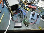
Here's the powersupply taken apart ready to take a new display unit
attachment.php


New digital panel meter
attachment.php


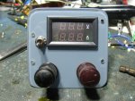
I used my mill again and cut a large rectangular hole on the front panel to accept the DPM and used a new toggle switch since the old one won't fit
attachment.php


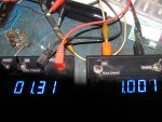
The old shunt I made measured 1.31mohm and I need a 75mV/100A shunt so I need to change it to 0.75mohm.
attachment.php


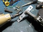
Drilled new holes and cut it shorter
attachment.php


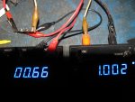
New resistance was a little lower than I was hoping at 0.66mohm but the DPM seems to have ample range to get the right display value
attachment.php


wired everything up and calibrated it on the bench and the amp calibration pot was nearly to the end but I was still able to get it right
attachment.php


I also decided to do the temp controlled fan mod based on this PDF I found.
IMG_3044_zps78213986.jpg~original


Wedged the sensor in between the main switching device heatsink fins
IMG_3047_zps02098fac.jpg~original


Put back the original fan since it was quieter vibration wise, compared to the replacement.
IMG_3046_zpsb5e7d26c.jpg~original


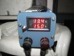
Here it is now charging a large battery bank
attachment.php


I hope this meter will last much longer than the previous one though I miss having the wattage display on it :P
 

Attachments

  • IMG_3015.jpg
    IMG_3015.jpg
    288.1 KB · Views: 518
  • IMG_3016.jpg
    IMG_3016.jpg
    258.3 KB · Views: 703
  • IMG_3018.jpg
    IMG_3018.jpg
    217.5 KB · Views: 569
  • IMG_3028.jpg
    IMG_3028.jpg
    224.6 KB · Views: 531
  • IMG_3032.jpg
    IMG_3032.jpg
    182 KB · Views: 531
  • IMG_3033.jpg
    IMG_3033.jpg
    234.3 KB · Views: 672
  • IMG_3039.jpg
    IMG_3039.jpg
    152.9 KB · Views: 585
  • IMG_3027.jpg
    IMG_3027.jpg
    139.4 KB · Views: 545
Last edited:


Back
Top