rhd
0
- Joined
- Dec 7, 2010
- Messages
- 8,469
- Points
- 0
I promised a harvest and teardown thread, and here it is!
First order of business. This is henceforth going to be called the Pico1, at least by me. If you think it's called something else, you must be mistaken. Out of respect to our community, the forum's owner, and the manufacturer of what is a phenomenal product, I'm not going to use their name, nor the name of their projector model. I would ask that everyone else do the same. If I see links added, or names thrown around in replies, I'll delete the content of this thread, or move it to the vets section.
I'm not going to preface this with information about the unit itself since that has been discussed elsewhere on this forum. In a nutshell, it contains a 450nm (440-460), a 640nm diode (635 to 645) and a 532nm green made by Corning that isn't actually DPSS, but also sadly isn't a diode (I knew this going in)
With nothing further, here is the walkthrough:
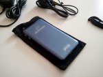
Top view, looking down. Preparing for surgery:

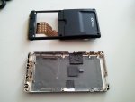
There are six screws to remove. The two screw holes on the far left were previously under a yellow sticker that comes off easily. The whole case comes apart easily.

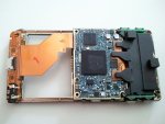
Flip it over, and this is what you'll see. I was shocked at how tiny the actual laser projection system is. It's hidden under the black plastic on the right:

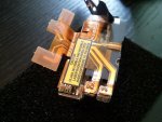
The black plastic comes off easily, to reveal the laser projection system. Note the three plastic clear tabs on top of the ribbon cable that attaches the laser projection system to the PCB. Those are the connectors that you'll want to unclip. They pop off easily. I used a wooden toothpick and just nudged them up slightly. It's easy to clip them back in too (something I did many times later).
Interesting note: If you were only in this for the two diodes, you could actually stop right here. The diodes are right in front of you. The RED is labelled LD1, and the BLUE is labelled LD2. The green module is underneath the yellow sticker, but it's a bit harder to remove at this stage.

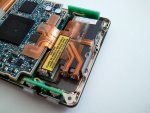
Some hex screws hold the PCB in place. If you don't have the right hex wrench (I didn't) then #1: you probably don't need to remove the PCB anyway, and #2: they aren't very tight, and a similar sized phillips head screwdriver with a bit of downward pressure actually had no difficulty unscrewing the hex screws, even though it was the wrong tool for the job. Here's what's left with the PCB removed.

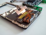
Good news, it's only a weak adhesive holding the laser assembly in place. It came off easily.

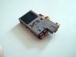
And the bottom of the assembly (note, the markets were NOT mine, they were obviously added at the factory):

The diodes (which, BTW are 3.8mm not the normal 5.6) and their heatsinks pop right off the body of the laser projection assembly. If you've ever removed a diode in its heatsink from a drive sled, then you'll be familiar with how they're affixed with a very mild adhesive. Almost no pressure or strength was required to pop them loose from the assembly.

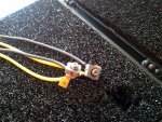
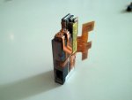
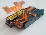
I cut the ribbon cables and this is what I was left with (after adding my own leads for a quick "survival test"). Good news, but diodes work!

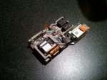
The assembly with the black plastic film removed from the top so that you can see inside.

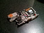
I'll explain what's going on based on the next photo (below this explanation):
Top left: The GREEN laser. Makes a 90 degree turn right, through the pink dichro, bounces off the "peach" coloured dichro making another 90 degree turn towards that red mirror in the far right of the assembly.
Two black things: Are collimating lenses for the RED and BLUE diodes. The dichros also direct their beams towards that red mirror in the far right.
Two clear plastic "balls": These are ingenious. I'm not sure if you can tell from the photo clearly, but the very top of them is fitted for a hex attachment. Basically, these are lenses in a spherical ball joint, that are positioned and tweaked at the factory to get alignment perfect. Once it is, a little bit of glue is put in place to keep them where they are.
The red mirror on the far right: This actually angles the beam downwards towards a mirror on the ground (which is really small, and not visible in this photo because the output window blocks view of it), which then bounces it back upwards into the MEMs DLP system (top right). The MEMs DLP system then pops the beam straight out forward through the glass in the bottom right corner. That is your projected image!

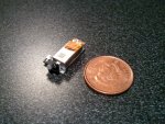
And finally, the Corning G-1000 directly doubled 1064, which produces a 532nm beam without the traditional DPSS process. This thing is tiny! I'm yet to get it running though.

First order of business. This is henceforth going to be called the Pico1, at least by me. If you think it's called something else, you must be mistaken. Out of respect to our community, the forum's owner, and the manufacturer of what is a phenomenal product, I'm not going to use their name, nor the name of their projector model. I would ask that everyone else do the same. If I see links added, or names thrown around in replies, I'll delete the content of this thread, or move it to the vets section.
I'm not going to preface this with information about the unit itself since that has been discussed elsewhere on this forum. In a nutshell, it contains a 450nm (440-460), a 640nm diode (635 to 645) and a 532nm green made by Corning that isn't actually DPSS, but also sadly isn't a diode (I knew this going in)
With nothing further, here is the walkthrough:
Top view, looking down. Preparing for surgery:

There are six screws to remove. The two screw holes on the far left were previously under a yellow sticker that comes off easily. The whole case comes apart easily.

Flip it over, and this is what you'll see. I was shocked at how tiny the actual laser projection system is. It's hidden under the black plastic on the right:

The black plastic comes off easily, to reveal the laser projection system. Note the three plastic clear tabs on top of the ribbon cable that attaches the laser projection system to the PCB. Those are the connectors that you'll want to unclip. They pop off easily. I used a wooden toothpick and just nudged them up slightly. It's easy to clip them back in too (something I did many times later).
Interesting note: If you were only in this for the two diodes, you could actually stop right here. The diodes are right in front of you. The RED is labelled LD1, and the BLUE is labelled LD2. The green module is underneath the yellow sticker, but it's a bit harder to remove at this stage.

Some hex screws hold the PCB in place. If you don't have the right hex wrench (I didn't) then #1: you probably don't need to remove the PCB anyway, and #2: they aren't very tight, and a similar sized phillips head screwdriver with a bit of downward pressure actually had no difficulty unscrewing the hex screws, even though it was the wrong tool for the job. Here's what's left with the PCB removed.

Good news, it's only a weak adhesive holding the laser assembly in place. It came off easily.

And the bottom of the assembly (note, the markets were NOT mine, they were obviously added at the factory):

The diodes (which, BTW are 3.8mm not the normal 5.6) and their heatsinks pop right off the body of the laser projection assembly. If you've ever removed a diode in its heatsink from a drive sled, then you'll be familiar with how they're affixed with a very mild adhesive. Almost no pressure or strength was required to pop them loose from the assembly.

I cut the ribbon cables and this is what I was left with (after adding my own leads for a quick "survival test"). Good news, but diodes work!

The assembly with the black plastic film removed from the top so that you can see inside.

I'll explain what's going on based on the next photo (below this explanation):
Top left: The GREEN laser. Makes a 90 degree turn right, through the pink dichro, bounces off the "peach" coloured dichro making another 90 degree turn towards that red mirror in the far right of the assembly.
Two black things: Are collimating lenses for the RED and BLUE diodes. The dichros also direct their beams towards that red mirror in the far right.
Two clear plastic "balls": These are ingenious. I'm not sure if you can tell from the photo clearly, but the very top of them is fitted for a hex attachment. Basically, these are lenses in a spherical ball joint, that are positioned and tweaked at the factory to get alignment perfect. Once it is, a little bit of glue is put in place to keep them where they are.
The red mirror on the far right: This actually angles the beam downwards towards a mirror on the ground (which is really small, and not visible in this photo because the output window blocks view of it), which then bounces it back upwards into the MEMs DLP system (top right). The MEMs DLP system then pops the beam straight out forward through the glass in the bottom right corner. That is your projected image!

And finally, the Corning G-1000 directly doubled 1064, which produces a 532nm beam without the traditional DPSS process. This thing is tiny! I'm yet to get it running though.

Attachments
-
 2011-06-01 17.11.36.jpg184.6 KB · Views: 6,381
 -
 2011-06-01 17.21.46.jpg199.7 KB · Views: 6,660
 -
 2011-06-01 17.22.16.jpg235.4 KB · Views: 7,196
 -
 2011-06-01 17.24.10.jpg267.8 KB · Views: 7,630
 -
 2011-06-01 17.28.40.jpg242.7 KB · Views: 8,758
 -
 2011-06-01 17.31.13.jpg192 KB · Views: 6,489
 -
 2011-06-01 17.34.22.jpg177.6 KB · Views: 6,632
 -
 2011-06-01 17.41.32.jpg218.3 KB · Views: 6,801
Last edited:


