

- Joined
- Dec 23, 2007
- Messages
- 2,494
- Points
- 0
Let the DAC handle it I would assume. I think the TTL on the board is for the pre installed stuff but I could be wrong.
Coincidentally, Analog will work fine with TTL. TTL is 0V off and 5V on, Analog is 0-5V with intensity increasing as voltage does. So an analog laser on a TTL input will behave the same as a TTL laser on a TTL input.
Coincidentally, Analog will work fine with TTL. TTL is 0V off and 5V on, Analog is 0-5V with intensity increasing as voltage does. So an analog laser on a TTL input will behave the same as a TTL laser on a TTL input.
Last edited:


") You beat me to it.
You beat me to it.

")
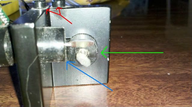
 They are multi-turn trimmers/potentiometers. Bourns makes them, however, I have no clue what model would cross ref to this. You say it's internally damaged, therefore it can't be soldered back onto the pcb?