Welcome to Laser Pointer Forums - discuss green laser pointers, blue laser pointers, and all types of lasers

Buy Site Supporter Role (remove some ads) | LPF Donations

Links below open in new window

FrozenGate by Avery

GB: Low Cost 15K Scanner Galvo Set with DMX & ILDA Complete - $75 **ARRIVED**

Let the DAC handle it I would assume. I think the TTL on the board is for the pre installed stuff but I could be wrong.

Coincidentally, Analog will work fine with TTL. TTL is 0V off and 5V on, Analog is 0-5V with intensity increasing as voltage does. So an analog laser on a TTL input will behave the same as a TTL laser on a TTL input.
 
Last edited:


Let the DAC handle it I would assume. I think the TTL on the board is for the pre installed stuff but I could be wrong.

Coincidentally, Analog will work fine with TTL. TTL is 0V off and 5V on, Analog is 0-5V with intensity increasing as voltage does. So an analog laser on a TTL input will behave the same as a TTL laser on a TTL input.

Correct, also the TTL on the show card are interconnected with pins 5, 6, 7, 18, 19, 20, on the DB25 connector. So you can use TTL output from the show card when not connected to a DAC, or you can use analog when a DAC is available.
 
Did you figure out your alignment problem Rocket? I'm having the same problem.

I started trying to bounce off of the bottom mirror first but I couldn't get the output centered on the 2nd mirror. Now I'm going off of the top mirror first (which works a lot better for alignment) but now everything is upside down. I tried flipping the galvos but it just turned the output on it's side.

I'm pretty sure I'm going to need bigger mirrors, these ones are too small for the output of any diode laser.

IMG_20110715_225159.jpg
 
Your galvo wires are backwards(unless you have them swapped on the board). match up the black sharpe on one of the galvo wires to the connectors on the galvos and the board. And I feed my laser through the other side, hitting the bottom mirror first.
Did you figure out your alignment problem Rocket? I'm having the same problem.

I started trying to bounce off of the bottom mirror first but I couldn't get the output centered on the 2nd mirror. Now I'm going off of the top mirror first (which works a lot better for alignment) but now everything is upside down. I tried flipping the galvos but it just turned the output on it's side.

I'm pretty sure I'm going to need bigger mirrors, these ones are too small for the output of any diode laser.

IMG_20110715_225159.jpg
 
Did you figure out your alignment problem Rocket? I'm having the same problem.

I started trying to bounce off of the bottom mirror first but I couldn't get the output centered on the 2nd mirror. Now I'm going off of the top mirror first (which works a lot better for alignment) but now everything is upside down. I tried flipping the galvos but it just turned the output on it's side.

I'm pretty sure I'm going to need bigger mirrors, these ones are too small for the output of any diode laser.

No I haven't fully fixed the problem. I did make it better, though.
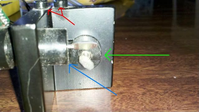
I loosened the socket head cap screw (allen) that holds the galvo motor in place (red arrows). Moving the galvos moves where the beam hits the mirrors.

galvo-1.jpg


The galvo with the green arrow adjusts where the beam hits the second mirror. Rotating it adjusts for levelness of the laser in relation to the galvo. I turned this and my image became a little better. Pulling the galvo in and out centers the beam on the second mirror. This really doesn't change much.

The galvo with the blue arrow adjusts the final projected image. Rotate it and the image projected goes either up or down on the projection surface. Pulling it in and out centers the beam on the mirror in relation to the horizontal projected image. This made the most improvement, but both sides of the image fade because of the beam hitting the galvo mount or going off of the mirror.

You can put bigger mirrors on and it will help. However, keep in mind that greater mass equals less performance and a reduced scan rate.

I believe that you can adjust the scanned image on the board. There are 14 multi-turn pots. Those should adjust scan angle and solve the problem. None of the trimmers are labeled, so it pretty much playing blind mans bluff. I haven't touched them yet. :beer:

Yea, I tried it upside down and sideways, too. Lol :D
 
I have the sharpie marks correct on mine. The beam enters the galvo just like the green arrow on my pic above.
 
I think these are set from the factory to be used upside down actually. When i plug in my DAC and project something using software. I have to flip the X Axis for the image to look right.
 
I think these are set from the factory to be used upside down actually. When i plug in my DAC and project something using software. I have to flip the X Axis for the image to look right.

:thinking: Hmm, that's odd. I haven't had the time to hook up my DAC yet, let alone install and set up my LSX. So, I don't know how mine will react, yet. ;)
 
I think I've figured out what the dip switches are for. These galvos work with DMX I believe, so the switches must be where the DMX address is entered. I do not have a DMX controller to verify this, but it makes sense. The DMX standard also calls for a five pin connector, so I think the 5pin connector on the board is where the DMX would go. Unfortunately I do not know what the pin assignment is yet. This is what I believe the switch assignment is:

Switch:-----------1--2--3--4---5---6---7---8----9----10
Purpose(D=DMX): D1 D2 D4 D8 D16 D32 D64 D128 D256 Mode(Sound/DMX
Edit:

I had a chance to power up the galvos, and so far everything seems to be working. I am hitting the lower mirror first like in the above picture, and it the image appears to be the correct way up. It could be backwards, but all I've been able to test is the built in animations. The horse/bird is running to the right, if that helps.
 
Last edited:
I received my set today! I have a problem, though. One of the "blue block thingy's" that is soldered to the PCB, with the adjustable pot on the side was broken loose. The leads were pulled out from the inside of the block, so I can't see a way to solder it back on. I'm not sure what this does, or how to set it, should I find a replacement. Does anyone have any ideas? Thanks, in advance. - Corbin
 

Attachments

  • 15k.jpg
    15k.jpg
    147.6 KB · Views: 665
Ooh. that's bad news. Sorry to hear this. :( They are multi-turn trimmers/potentiometers. Bourns makes them, however, I have no clue what model would cross ref to this. You say it's internally damaged, therefore it can't be soldered back onto the pcb?
 
A replacement set would be nice, since it appears to be assembly error on the part of the manufacturer that caused the part to come off. Its difficult to see in the pic, but it looks to me like 1 or more of the pot's leads are broken off, which would make it very difficult to re-solder. The are however a very common part and can be easily purchased for only a couple bucks. Look on the sides of the pot and see if there are any identification markings. if not, twist it all the way to one side and meter the pins. Use this information to source a new one from digikey or a similar store.

I would not try to turn the set on until that is replaced, as it could cause damage to the galvos.
 
Ooh. that's bad news. Sorry to hear this. :( They are multi-turn trimmers/potentiometers. Bourns makes them, however, I have no clue what model would cross ref to this. You say it's internally damaged, therefore it can't be soldered back onto the pcb?

Yep, the pins coming out of the "adjustable blue block thingy's"lol, are broken off internally. The pins are still on the PCB. I suppose I could find some replacement pins and glob some solder in the holes, then attempt to resolder it to the PCB with hopes for the best?:undecided:


Back
Top