Welcome to Laser Pointer Forums - discuss green laser pointers, blue laser pointers, and all types of lasers

Buy Site Supporter Role (remove some ads) | LPF Donations

Links below open in new window

FrozenGate by Avery

FS: White Fusion Laser Mixing Kit


Yes ok, I've seen these video's before, nice!
But I want too seen more! :D
At these video It's not really clear how big the 'show' wil be. Maybe from al longer distance and a overview in the room? Or a video outsite in the garden or something , @ party with some audience!? :D
 
Ones my laser is done I will deliver. But I can't find any stinkin batteries for it! :yabbmad:
 
Ones my laser is done I will deliver. But I can't find any stinkin batteries for it! :yabbmad:


Speaking of Batteries. I was wondering if 9V is really the minimum for your driver FML or if it's 5.?V for the BRD + 1.5 for the DDL drivers V drop. That would mean a 7.4V LiPo like this one could be used. 10C 7.4V 1200mAh 2S Rx LiPo Battery :: LiPo Batteries :: Battery Packs :: Batteries/Chargers :: Advantage Hobby


I would gladly trade the Voltage for maH with these builds. With the way LiPos discharge we might get more play time per charge this way. At the moment I get about 45min for my 6x build with a fan. MisterWilling reports 30min with his 8x build no fan.


I will also see about doing another video when I have time. I just stink at putting music to it and all that so mine are kind of bland. It will also mean having to clean up my basment where I can have the fogger going :D


-Ryan
 
The voltage drop is ~3V.
3 + 5.2 (BR) = 8.2V. Then I give it 0.8V of extra tolerance so you don't get below the voltage needed for the regulators to operate properly. So 9V minimum.

Edit: I get that the runtime is not that great, but don't forget that it is allot of total currant and high power, really we should use lager hosts to fit larger batteries.
 
Last edited:
Anyone care to tell how to install the powerjack? I've been trying to figure it out but I can't tell just from the pics. I'm an electronics n00b :(

I'm guessing when you buy a 9-12V DC adapter and jack, you just solder the power wires to the jack?

Any web links to the supply/ jack?

Thanks.
 
Last edited:
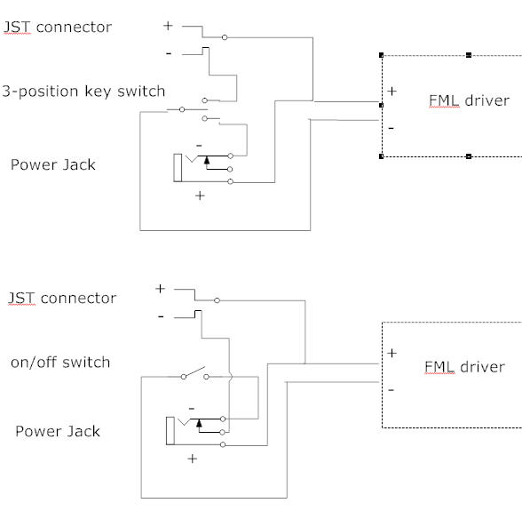
There are two ways I could have added the power jack.

Power%20Schematic.jpg


The top schematic is the way I did it because the key switch is a 3 position switch and I can select battery or PSU input with it. The bottom schematic will also work as long as the jack has a built in switch like many do. The switch in the jack will toggle in the battery power when the Male jack is not plugged in. And disconnect it when the it is plugged in.

Edit: The center pin of the power jack is wired as the positive polarity in my build. This diagram doesn't illustrate that well.
 
Last edited:
Sightfx or misterwilling, I have a favour to ask you. My host will arrive soon but I still haven't found any batteries. Other than that I have all the other parts I need for final assemble. I predict that finding a battery and have it arrive will take a long time...
So I want to make a dummy-battery so I know where to place the other parts and get it working as soon as possible. I need some very detailed measurements (in metric if you can) of the battery, and a couple of photos. This is greatly appreciated!
 
55mm X 30.11mm X 21.2mm


I can do you one better if you are using the clear enclosures Jayrob found that we've all been using. Digi-Key - HM958-ND (Manufacturer - 1591BTCL)

If this is the enclosure you can line up your driver to the edge of the hammond stamp furthest away from the short side of the enclosure. This will put the PIC 21mm away from the posts inside the enclosure. My battery sits on top of the board a bit but before the pic. The Kit is mounted at a bit of an angle so that the Red HS and the bottom corner of the sled fit between the posts on the other side. My mounting hole is 20.5mm from the long edge and 16mm from the short edge. You may need to adjust from that so that your heat sinks don't press against the enclosure. I would start by making a 5mm hole at those measurements and if you need to adjust it you can either make it a 6mm hole or use a round file to move the mounting hole in the direction you need.


EDIT: I should also note that I had to bend the transistor next to the violet regulator so it wouldn't rub against the Red Heat sink. You can see it in the picture I have in my post above.


I hope this helps.


I will add to the tutorial section soon.


Cheers :beer:

Ryan
 
Last edited:
Thanks! I have ordered an aluminium box that looks just like the plastic one, I hope that the dimensions are the same, I had very little info about it. If it works it will be a TIGHT fit for sure. I will do some work in the box and maybe on the HS as well and hopefully make it sit straight.
 
Let us know what box you use. I tried to teach my nephew how to build these kits and he made some mistakes that caused cosmetic defects. I will be listing them in the discount section soon and an all aluminum enclosure would be a great recommendation to use with them.

Thanks,

Ryan
 
Last edited:
Thanks for the schematic sightfx! The jst connector goes to the battery?
 
Last edited:
Yes,

That is one of the standard battery connectors for RC hobby batteries.


Back
Top