Welcome to Laser Pointer Forums - discuss green laser pointers, blue laser pointers, and all types of lasers

Buy Site Supporter Role (remove some ads) | LPF Donations

Links below open in new window

FrozenGate by Avery

FREE DIY open source BOOST driver!!! Tested & working!!

Yea I dont know what the v drop of the diodes are he used.. NF034G U1520 is the part number. U1520 ultra fast rectifier diodes.. Just got home from work this has been bugging me all day... I'm going to search his thread again to see. I have a friend I am going to bug to test with his new Fluke mm to see if that may be part of my problem. I'm going to have to break down and buy a good one anyway's but I got that laser hobbyist pocket atm..


Yea I dont know what the v drop of the diodes are he used.. NF034G U1520 is the part number. U1520 ultra fast rectifier diodes.. Just got home from work this has been bugging me all day... I'm going to search his thread again to see. I have a friend I am going to bug to test with his new Fluke mm to see if that may be part of my problem. I'm going to have to break down and buy a good one anyway's but I got that laser hobbyist pocket atm..

Do you have a picture of the test load/diodes?
 
I made this video the other day and I beleive it accuratly shows the forward voltage for the Red and Blue setting based on the input current on Jeff's test load. And it does look like the forward voltage will increase as the current being given is increased. I used this to show someone why I used the red setting to set 445 drivers.


Last edited:
yep dtr is right,

I also use 3 or 4 diodes on my test load for 445 high currents.

that's why I always use two multimeters one for the output voltage from the driver to the test load and one across the resistor for the current.

It's easier to keep track on things that way :beer:
 

Thanks Blord. That explains a lot. My test load has a bunch of round, black diodes with it fat thick leads and looks nothing like that, so when I found a data sheet I wasn't sure that I had found the right one.

I'll post it here in a second...

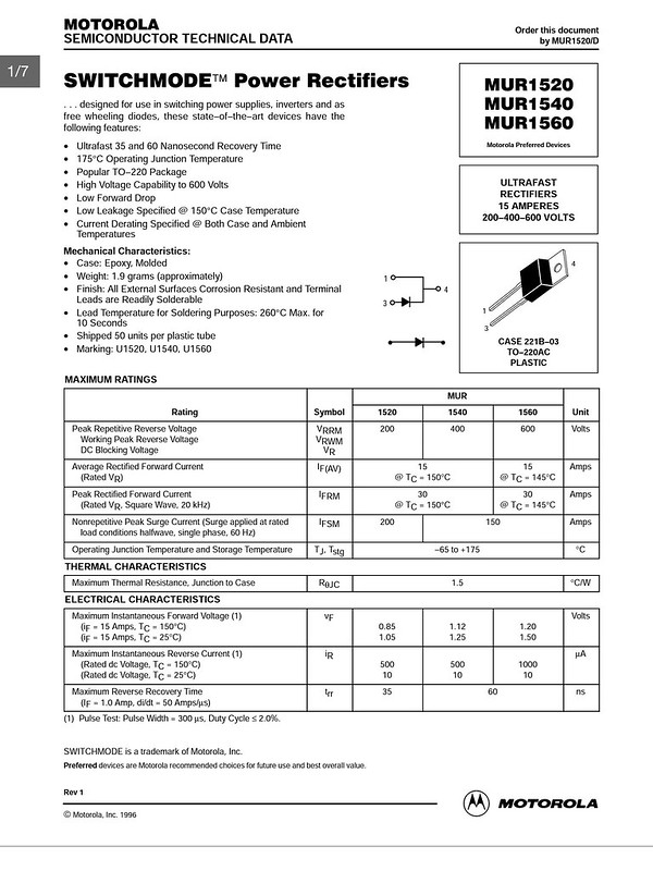
Motorola MUR1520 Switchmode Rectifier ULTRAFAST RECTIFIERS 200V/15A

It looks like 1.05v - I think.

SWITCHMODE Power Rectifiers

. . . designed for use in switching power supplies, inverters and as free wheeling diodes, these state–of–the–art devices have the following features:

• Ultrafast 35 and 60 Nanosecond Recovery Time
• 175°C Operating Junction Temperature
• Popular TO–220 Package
• High Voltage Capability to 600 Volts
• Low Forward Drop
• Low Leakage Specified @ 150°C Case Temperature
• Current Derating Specified @ Both Case and Ambient Temperatures

Mechanical Characteristics:
• Case: Epoxy, Molded
• Weight: 1.9 grams (approximately)
• Finish: All External Surfaces Corrosion Resistant and Terminal Leads are Readily Solderable
• Lead Temperature for Soldering Purposes: 260°C Max. for 10 Seconds
• Shipped 50 units per plastic tube
• Marking: U1520, U1540, U1560
 
Last edited:
Sorry I got tied up Weekends are crazzy at the restaurant.. Yes that is my test load. I found the datasheet but I couldnt see the drop on it anywhere. Maybe that just wouldnt be on the specsheet.
 
Well, someone jump in and correct me if I am wrong - but I am assuming it is the Vf or Maximum Instantaneous Forward Voltage at 25C.


Motorola by tsteele93, on Flickr
 
Last edited:
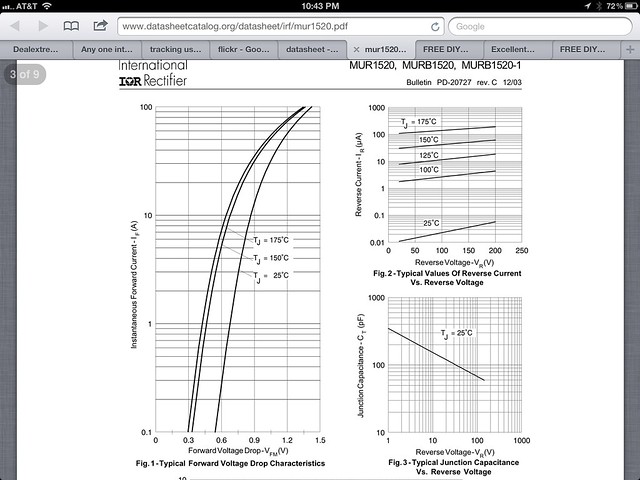
If you look to the left side it says at 15A. Somewhere on that datasheet it should have a graph showing the voltage at different currents.

Of course the best way would be to just measure the voltage over the test load instead of trying to calculate it.
 
You mean we aren't driving the diode at 15 A?

:D

Thanks (again) Ben, I'll go through the data sheet.

Looking at the graphs, at 1A it looks very close to a typical 0.7V

MUR1520


Motorola 2 by tsteele93, on Flickr
 
Last edited:
Weee 15A LD! woot W00t! :lasergun:

I love it when I get to use that!


When I tested the V from the driver to the test load it was very low.. I'm thinking my MM is totally wrong it was measuring under 2V with the 3V battery and under 3V with the samsung at over 4V. It allmost looks like it is bucking... This cant be right...
 
What do you mean when you say that you "tested the V from the driver to the test load"...?

I think you're using your dmm wrong.
 
well from my limited understanding I conected the +out of the driver to my mm then the out of my mm to the test load.
 
Honestly I'm going to get a good mm this is a waste of time for all of you..
 
Honestly I'm going to get a good mm this is a waste of time for all of you..

It seems like I've been saying this a lot lately....

It's not the tools that are at fault. People need to stop blaming their equipment / components for everything. This is no exception. The problem isn't your DMM, nor the driver.
 
Last edited:
well from my limited understanding I conected the +out of the driver to my mm then the out of my mm to the test load.

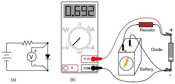
That isn't how you want to do that, here - check this out...

Meter check of a diode : DIODES AND RECTIFIERS

If you would like to measure a diode's forward voltage drop at some non-trivial current, the circuit below can be wired up using a battery, resistor, and voltmeter.


Voltage Drop by tsteele93, on Flickr


Measuring forward voltage of a diode without“diode check” meter function: (a) Schematic diagram. (b) Pictorial diagram.
 
Last edited:


Back
Top