Welcome to Laser Pointer Forums - discuss green laser pointers, blue laser pointers, and all types of lasers

LPF Donation via Stripe | LPF Donation - Other Methods

Links below open in new window

ArcticMyst Security by Avery

DIY Thermal LPM for under $50


TTerbo

0
Joined
May 20, 2010
Messages
1,361
Points
0
i dont have it yet i ordered that one in the link.
cheers
 

HIMNL9

0
Joined
May 26, 2009
Messages
5,318
Points
0
BTW, can i suggest you to use the second, unused op-amp as follower at the output of the first one ? ..... in this way, you may reduce the interference of the voltmeter, if is not a high-impedance unit.

Or also, make it as an output stage with a little variable amplification coefficent, for have a "fine tuning" in the calibration process .....
 
Joined
Jul 27, 2007
Messages
3,642
Points
63
have a look at the link. and how comr in the diagram the pot has 4 leads?
and instead of 1kohm can i use 1.5kohm and instead of 5kohm use 3.7kohm?
cheers

Yes the pot has 4 leads on the pcb as some trimpots have the pins all in a line while others have the wiper lead offset from the rest.

Be careful when substituting the resistors in the circuit as they are what defines the gain in the amplifier circuit. You can try your resistor values but you may not get the gain level you want.


If you mean on the PCB, the trimmers don't have 4 leads, only 3 ..... this pads disposition is made automatically from some softwares, cause in the market there are trimmers that have the 3 leads inline, and others that have the 3 leads placed in a "triangular" disposition ..... the central pads are connected together.

Exactly :)

About the link you posted, the LM358 datasheet shows clearly that the IC is an 8-pin DIP ..... where you see it with only 6 pins ? :confused:

BTW, can i suggest you to use the second, unused op-amp as follower at the output of the first one ? ..... in this way, you may reduce the interference of the voltmeter, if is not a high-impedance unit.

Or also, make it as an output stage with a little variable amplification coefficent, for have a "fine tuning" in the calibration process

.....

That's definitely a good idea, although the LM358 is rated to 30mA of output current so that should be plenty for pretty much all voltmeters.
The idea is to use a multi-turn potentiometer for the gain setting for precise calibration, but this would also work well.
 

Benm

0
Joined
Aug 16, 2007
Messages
7,896
Points
113
Since its there anyways, using it as a buffer or extra correction stage would be a good idea. Some people prefer multi-turn pots, others 2 'normal' pots for fine and course adjustment. The latter could easily be realized by adjusting the buffer amps gain slightly.

Also, if you are not using an opamp, dont connect both pins to ground and let the output remain unconnected. You should connect the output to the - input and the + input to ground.

Connecting both to ground results in amplifying offset voltages by infinity, which isnt good since those offsets can vary with temperature, possibly leaving the omamp output flappering between ground and supply voltage randomly.
 
Joined
Jul 27, 2007
Messages
3,642
Points
63
Since its there anyways, using it as a buffer or extra correction stage would be a good idea. Some people prefer multi-turn pots, others 2 'normal' pots for fine and course adjustment. The latter could easily be realized by adjusting the buffer amps gain slightly.

Also, if you are not using an opamp, dont connect both pins to ground and let the output remain unconnected. You should connect the output to the - input and the + input to ground.

Connecting both to ground results in amplifying offset voltages by infinity, which isnt good since those offsets can vary with temperature, possibly leaving the omamp output flappering between ground and supply voltage randomly.

Thanks, I will update the schematic when I have some time
 

Benm

0
Joined
Aug 16, 2007
Messages
7,896
Points
113
You're welcome :)

I suppose this kind of power meter could also be calibrated by using a heater, temporarely connected to the tec's side the laser irradiates. That would eliminate the need for a laser of know power, which makes things more reproducible.

I suppose one could temporarely bond a SMT resistor to the face the laser shines on, for example 100 ohms at 5 volts (resulting in 250 mW). Using some removable thermal compound, i think such a think would be feasible, allowing re-builders to calibrate the unit prior to painthing the tec.

I've tried thermal calibration on other thermal measuring devices, with variable results. You won't get the response spot-on, but down to the order of 10% deviation is feasible, which could be good enough for many users... just for getting a general idea about the power output of some laser device.
 

HIMNL9

0
Joined
May 26, 2009
Messages
5,318
Points
0
About the calibration, i have a different suggestion.

The method that you have posted, is a good system when you already know the reflection/absorption index of the TEC plate and paint layer, but can give some imprecision, if used with unknown TECs systems ..... i mean, anyone can have a different TEC, with different surfaces (bare ceramic, gold plated, indium tinned), and can use the paint that they find in their stores, and you probably know that these paints have a lot of different reflection/absorption coefficents .....

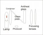
I'm trying to build something reproducible, using a specific filament lamp and lenses that can be found easily (still works in progress, sorry) ..... anyway, the principle is the following one: if i get a lamp type that can be found almost all around the world (as example, car lamps, that are more or less standardized both in production and distribution), and focus the filament image on a certain dimension on the reading plate, with a precise voltage, i can build, probably, a decent thermal calibration system that is independent from the plates and paint layers .....

So, regardless, if one have a 5mm TEC with acrylic black, or a 8mm TEC with exhaust tubes paint, or anything other, you can calibrate it for the right value, cause the assembly send always the same power to the reading face .....

Actually i discarded the "signal" lamps (too much incostants), and i'm experimenting with H1 lamps, and H4 lamps using the shielded filament, and had some decent result as "constant emission vs power supply" from osram and philips lamps, and horrific :p results using the "chinese" or streetmarket cheap ones ..... who know what brand is the more diffused one, or if there's any other more "stable" ? (only standard lamps, not the "blue glass" or strange others, need that the lamp can be found a bit everywhere with the same characteristics)
 

Benm

0
Joined
Aug 16, 2007
Messages
7,896
Points
113
The thermal test with a resistor doesnt consider any reflection from the paint, just assumes 100% absorption. I'm not entirely sure how valid that assumption is, but when more than a few percent of light is reflected or scattered off the sensor plate, you should be able to see that.

The lamp test as you describe would be good, with a few 'buts':

One is the variability of the lamps as you mention. This could perhaps be remedied by closely monitoring voltage and current, so that the lamp outputs the same amount of power regardless of small variations. We're talking only percents here though, otherwise the efficiency of the lamp changes and it's no longer valid.

The other, imo worse, problem, is that lightbulbs emit a lot of IR, and this extends pretty deep into the IR range. You would need to have a paint that absorbs well into the IR, which probably exist, but could be difficult to verify. If the paint has a high albedo in the IR, the results would be entirely invalid since a lot of the lamps output isnt absorbed by the sensor.
 

HIMNL9

0
Joined
May 26, 2009
Messages
5,318
Points
0
I was experimenting with an active feedback, that take part of the output light with a piece of glass placed angled in the light path, for keep the lamp emission constant, and one of these "anti-heat" glasses from diapositive projectors for take away the most part of the IR ..... being more precise, a system like this one (very schematic)

attachment.php


I have already obtained some decent results, but with some limitations .....

First, it cannot be a "continuous scale" system, i mean, you cannot make it continuously variable ..... you can, anyway, set more than 1 level of output, like, 10mW, 50mW, 100mW, and so on, and use different trees of regulation for the feedback ..... second, it need some seconds for stabilize itself, like from 30 to 60 seconds, before the level get stable (probably cause the filament change its intrinsec resistance when it change temperature, and this reflect on the feedback system) ..... and third, i made some tests using the parts of an old diapositive projector that i had here to mangle, but for have it efficent and repetible enough, i have to found a source for lenses that anyone can access, and repeat all with lenses that anyone can get (there is no sense in making something that work, if it work only with parts that 99% of the peoples cannot get :p)

Also, the distance still influence the reading in some way, but this can be easily solved making it for a constant distance (like, placing a ruler or a piece of something long, like, 20cm, in front of it, and using it as stopper for the reading head)
 

Attachments

  • calibrator01.jpg
    calibrator01.jpg
    52.9 KB · Views: 1,516

Benm

0
Joined
Aug 16, 2007
Messages
7,896
Points
113
Its a cool idea, but a bit elaborate to build as a replicable calibration source.

The feedback idea is good in itself, but it does 'move' the problem: not all photocells are equal even with the exact same part number, yet you have to rely on this part of the setup being accurate.

I suppose the easiest solution would be finding a paint that absorbs both visible and IR well and is commonly available. In that case you only need to know the sensor surface area (which you do) and you can calculate the power for a lightbulb of given power and distance from the sensor.

Personally i've only used a resistor as the heater calibration source, and got to within 10% accuracy using that. I realize that 10% is not very good for a measurement device, but it does give you a good indication of whats going on and allows you to gauge if a laser pointer is close to spec.
 

HIMNL9

0
Joined
May 26, 2009
Messages
5,318
Points
0
@ Benm: the better paint that i've found til now, is matte black for high temperature use (exhaust tubes for motors), when painted in a certain way, it make a very opaque layer ..... first layer, normal paint, left dry some hours ..... second layer, normal paint, left dry 10 minutes, then add a "third layer" keeping the can 40 or 50 cm away, and making "rainfall" the jet with very short pulses ..... at a certain point, this turn the second layer in an extremely corrugated surface, with high absorption index ..... (not yet tried with only one layer plus "rainfall", the next small TEC i found, will become an experimental subject :p)

The better way i heard can be black anodization, but as far as i know, is virtually impossible to obtain on a non-metallic surface ..... wondering if the anodization process can be made on the side of a TEC with gold plated layer, without destroy the TEC or the gold coating ..... maybe a low current process keeping the TEC plate with only the gold layer in contact with the surface of the liquid ..... can require a complicate setup, anyway .....


@ tterbo: not for low powers ..... a 40x40mm plate have a thermal mass too high, for react to low powers .....
 

Asherz

0
Joined
Jan 18, 2009
Messages
1,623
Points
0
I had one of these setup but with a lot less stuff in it,

Basically just wired the TEC onto a pot, from there two pins to my volt meter to get a reading, I got readings but the issue was I have nothing to calibrate with :(
 
Joined
Jul 27, 2007
Messages
3,642
Points
63
My setup was surpisingly sensitive - I was able to measure lasers down to 0.1mW using a meter capable of reading 0.0001v although the response time of a TEC is not near as fast as the Ophir radial thermopiles that I've been using for the Kenometers and stuff.

The TEC I used was a tiny 10x10mm from a dead TO-3 laser diode I got in a junk box from heruursciences. Mouser and Digikey have 15x15mm TECs for about $15 each that would work well.


Top