Welcome to Laser Pointer Forums - discuss green laser pointers, blue laser pointers, and all types of lasers

Buy Site Supporter Role (remove some ads) | LPF Donations

Links below open in new window

FrozenGate by Avery

DIY Laser Power Meter

Ken..I was only trying to find the proper meter for my project....

You told me straight out that the meter you used required a dedicated voltage source...and after looking around noticed that some meters needed a dedicated or Isolated source..while others did not..

I was not trying to cast dobt on your meter as a whole...but rather I am searching to discover now which meters would require a seperate voltage source, and which meters could use the power already there...

I've seen the $4.45 meters on ebay that Asia Engineer (giorgio11185) sells.....I believe that these are great meters..and appear identical to the meter that you use....

I also agree that a meter that can share the power source is a much more elegant solution......
Since you are also looking to go this way..I see that you also believe that there is a better solution available.

If you find a good meter solution...let me know!!!
You have been very good at finding items of interest......
I can only imagine what other projects you are working on.

LarryQ


the meter you've indicated from asia engineer is precisely the meter I got, and it's not suitable as it needs isolated power from the read.

I wasn't raggin on ya! LOL I know that your only trying to solve this portion and I'm trying to do the same thing. I've actually run into a nice meter that's pretty small and I'll have the link at the bottom of this post.

I don't want people to think I am against this project. I'm not. I'm upset that it's eating up all the boards I could be makin meters off of but heck that's really no thing in the big picture. I'm glad that folks can utilize these to get a good meter. Although with this method calibration is a factor. If you don't have a meter to test the readings and set from a baseline it's hard to do. if not impossible. needless to say, I'll probably be using this to make one for myself and see how it performs compared to the modifications I'm doing to the boards.

One thing for sure I'm going to use and hopefully knimrod will sell them to me premade is those pc interface boards.
Link below.


http://cgi.ebay.com/ws/eBayISAPI.dll?ViewItem&rd=1&item=350019290837&ssPageName=STRK:MEWA:IT&ih=022
 
Kenom said:
I'm glad that folks can utilize these to get a good meter.  Although with this method calibration is a factor.  If you don't have a meter to test the readings and set from a baseline it's hard to do. if not impossible.  needless to say, I'll probably be using this to make one for myself and see how it performs compared to the modifications I'm doing to the boards.


Oh no..  Calibration is not really a factor with the DIY meter presented here.  That's the beauty of this project.  It's the Coherent sensor head that's already calibrated at 1uV per mW.  All we have to do is make an amp that scales up the voltage accurately.  Our amp has a precise gain of 1000 which gets us our 1mV per mW for reading with a multimeter or DPM.  
 
>:(
Grr - Looks like my sensor head is dead.
Built the circuit - no output change when I point various lasers at it.
Made a 120uV voltage divider and hooked it in place of the sensor, and I see the 120mV output.
Oh well. I guess they did say "as is".
(I noticed the fuse was blown on the board - I wonder if that's related.)
 
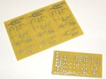
The PC Boards have arrived. :)

It's great fun cutting them apart and if you ordered more than one board, you get to cut them apart yourself. : ::)
 

Attachments

  • DSCF0795.JPG
    DSCF0795.JPG
    67.6 KB · Views: 395
Assembled PC Board. I'll be testing this later tonight.
 

Attachments

  • DSCF0798.JPG
    DSCF0798.JPG
    64.4 KB · Views: 1,133
Initial testing complete.  It works perfectly.  8-)

Because the sensor head is factory calibrated to output 1uV per mW, we can presume that having an accurate amplifier gain of 1000 will yield our desired amplifier output voltage of exactly 1mV per mW.

I preset my gain pot to 6.3K and powered it up.  The power measurements track perfectly with my prototype meter and also with my Coherent 210 thermal power meter.  The only calibration I did was measure my feedback resistors and calculate the preset value for the gain potentiometer.

The amplifier's gain is determined by the resistors in the feedback loop of the op-amp.  Gain in this case is (R2+R3+R4+VR1)/R2  [(100+47K+47K+5.9K)/100=1000].

I have suggested a pre-set value of 5.9K for the gain potentiometer, VR1, assuming that all the resistors in the amplifier will be accurate to their indicated values.  The reality is that since we are using resistors with a 5% tolerance rating, it stands to reason that the accuracy could be affected by up to 5% (or more) if using the suggested VR1 pre-set value of 5.9K.  We want our DIY meter to be as accurate as we can get so we should calibrate it.  We can either compare the laser power measurement to a known standard and adjust the gain pot accordingly or, we can calibrate the gain of the amplifier.  We can do this by carefully measuring the resistors that set the amplifier's gain (R2, R3, R4) and then calculate the correct pre-set resistance for VR1 to give us our gain of 1000.   Here is the formula: VR1=(R2*1000)-(R3+R4)-R2.    

My resistor measurements were as follows:
R2=99.1
R3=46.4K
R4=46.3K

So the calculation was: (99.1*1000)-(46400+46300)-99.1 = 6300.9 (or 6.3K)

All that said, if you use the 5% resistors and just pre-set VR1 to 5.9K, chances are you will be very close to an accurate calibration.
 
Zarniwoop said:
>:(
Grr - Looks like my sensor head is dead.
Built the circuit - no output change when I point various lasers at it.
Made a 120uV voltage divider and hooked it in place of the sensor, and I see the 120mV output.
Oh well.  I guess they did say "as is".
(I noticed the fuse was blown on the board - I wonder if that's related.)

That sucks that your head is doa! I'm going to have to check each one and make sure they are all good now!
 
OK!!!

I started to layout my project box today.

I have to say that for a while I did not think this box was going to have enough face area for what I wanted to do...

But it all fit!!

Like it was designed for this layout!!!

I decided to place a Green LED Pilot light on the face of the meter...I think it is going to look really great powered up!!!

Here is a Photo....and sry about the quality...I am no photographer!!!

005.jpg


Can't wait for the boards to get here!!

LarryQ

Here is a Picture!
 
All PCBs from the first group buy were sent today via USPS first class mail. The post office tells me 1-3 days for delivery.
 
LarryQ said:
OK!!!

I started to layout my project box today.

I have to say that for a while I did not think this box was going to have enough face area for what I wanted to do...

But it all fit!!

Like it was designed for this layout!!!

I decided to place a Green LED Pilot light on the face of the meter...I think it is going to look really great powered up!!!

Here is a Photo....and sry about the quality...I am no photographer!!!

005.jpg


Can't wait for the boards to get here!!

LarryQ

Here is a Picture!

That looks great! Nice work! What enclosure is that and what panel meter?
 
knimrod said:
All PCBs from the first group buy were sent today via USPS first class mail.  The post office tells me 1-3 days for delivery.
Sweet!
 
Knimrod,
Great job on the boards, thank you ;D
That looks great!  Nice work!  What enclosure is that and what panel meter?  
Back to top    
 
I am very interested in this info as well.


Back
Top