Benm
0
- Joined
- Aug 16, 2007
- Messages
- 7,896
- Points
- 113
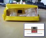
It has been a while, but i've been doing some work on it again. I've slightly modified the sensor design, greatly reducing problems with convection and airflows, and also improving the response times a little.
See the picture for the prototype, and sensor diagram.
The new version sits on a 0.6mm copper support wire, that also serves as the main heat transfer sink. Component wires are thinner, but also draw away some heat obviously. The resistor was changed to a smd type, which reduces thermal mass, and gets enough heatsinking to do to the 250 mW calibration as its mounted.
The support wire and components are fixed to the plate using a very thin layer of cyanoacrylate glue. For the isolation i've used some bubble wrap for the prototype - a styrofoam cut-out would work better.
Thanks to Warske for sending me some materials. I've also tried the really thin foil, which is cool stuff: it improves speed quite dramatically, but is so thin it doesnt spread the heat evenly... using that material, you get different readings if you hit the sensor plate in different areas.


