Benm said:
I am a bit puzzled why the results are too high, i expected them to be too low due to light not being absorbed and all. Somehow the laser seems to do a better job at heating the sensor than the resistor does... perhaps a matter of mechanical design.
First, very interesting thread! Great job!
As I mentioned on another thread, I have two ideas about why the results might be too high.
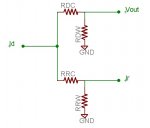
The first idea is a bit complicated to explain. To help with that I made a very simplified thermal model of your sensor, neglecting convection and radiation losses, and concentrating on the leads of the diode and resistor (see pic).
In the thermal model
- temperature is modeled as voltage
- thermal power is modeled as current
- thermal resistance is modeled as resistance
Assume the metal plate has zero thermal resistance.
Id - the power from the laser diode that is absorbed and converted to heat. Some power is reflected, so your meter should read low. To simplify, assume all the power is absorbed.
Ir - the power from the 0.25 W resistor.
Vout - the temperature of the diode junction, which generates your output reading.
RDC - the thermal resistance from the diode junction to the metal plate (through the Diode Case).
RDW - the thermal resistance from the diode junction to ambient (through the Diode Wires).
RRC - the thermal resistance from the resistor junction to the metal plate (through the Resistor Case).
RRW - the thermal resistance from the resistor junction to ambient (through the Resistor Wires).
Now, what we hope will happen is that if we apply laser power to the black surface of the metal plate, or we apply the same amount of electrical power to the resistor, each will give us the same temperature rise above ambient at the diode junction.
To test this with the thermal model, assume initially that each resistor is 1 ohm.
If we apply 1 amp of current at Id (modeling the laser), then Vout will be 0.5 v.
If we apply 1 amp of current at Ir (modeling the power from the resistor), then Vout will be 0.25 v.
So we would actually have to have twice as much current at Ir as at Id to match the Vout.
We see that, if the model is correct, the laser power is overestimated. Since we don't actually know the real value of the resistances, we don't know exactly how big this effect is.
The thermal model also tells you that for Vout to be the same when each input is the same, then RRC must be zero and RRW must be infinite.
The first means that you get improvement if you have better thermal coupling between the carbon film resistance element and the metal plate. So, for example, a 1 W surface mount resistor would likely give you better coupling, since it is thin and flat and there is no case material to separate it from the metal plate. eg:
http://search.digikey.com/scripts/DkSearch/dksus.dll?Detail&name=PT100AFCT-ND While this should be an improvement, it is still not perfect.
The second means that you get improvement if you increase the thermal resistance of the resistor leads by using much thinner wire. Note that this doesn't apply to the leads on the diode. You can also use thermally conductive epoxy to cement these thinner leads to the metal plate. This changes the thermal model in a favorable way.
If you increase the thermal resistance of your resistor leads, your thermal time constant will increase, which you mentioned in a previous post as being undesirable. You can reduce the time constant again by attaching similar leads directly to the metal plate using thermally conductive epoxy.
There are still effects due to radiation and conduction losses which make the situation imperfect, but the above should be an improvement.
The second idea is that I didn't see where you account for the temperature coefficient of the heater
resistor. As it heats up, its resistance will increase and it will provide less power than expected based on just the voltage across it. But I may have missed where that is accounted for.
This looks like a great project which gives very useful measurements.


