Welcome to Laser Pointer Forums - discuss green laser pointers, blue laser pointers, and all types of lasers

LPF Donation via Stripe | LPF Donation - Other Methods

Links below open in new window

ArcticMyst Security by Avery

DIY: Laser Power Gauge

Benm

0
Joined
Aug 16, 2007
Messages
7,896
Points
113
It has been a while, but i've been doing some work on it again. I've slightly modified the sensor design, greatly reducing problems with convection and airflows, and also improving the response times a little.

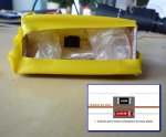
See the picture for the prototype, and sensor diagram.

The new version sits on a 0.6mm copper support wire, that also serves as the main heat transfer sink. Component wires are thinner, but also draw away some heat obviously. The resistor was changed to a smd type, which reduces thermal mass, and gets enough heatsinking to do to the 250 mW calibration as its mounted.

The support wire and components are fixed to the plate using a very thin layer of cyanoacrylate glue. For the isolation i've used some bubble wrap for the prototype - a styrofoam cut-out would work better.

Thanks to Warske for sending me some materials. I've also tried the really thin foil, which is cool stuff: it improves speed quite dramatically, but is so thin it doesnt spread the heat evenly... using that material, you get different readings if you hit the sensor plate in different areas.
 

Attachments

  • laser-newsensor.jpg
    laser-newsensor.jpg
    140.1 KB · Views: 317


Benm

0
Joined
Aug 16, 2007
Messages
7,896
Points
113
Some shots of the new sensor at work.
 

Attachments

  • laser-newsensor-50mw-cr2.jpg
    laser-newsensor-50mw-cr2.jpg
    174.7 KB · Views: 266
  • laser-newsensor-dilda.jpg
    laser-newsensor-dilda.jpg
    174 KB · Views: 307
  • laser-blueray.jpg
    laser-blueray.jpg
    176.9 KB · Views: 277
Joined
Sep 20, 2008
Messages
17,622
Points
113
Hey Benm...

nice work... any schematic or parts update for your finished LPM...:yh:


Jerry

You can contact us at any time on our Website: J.BAUER Electronics
 
Last edited:

Benm

0
Joined
Aug 16, 2007
Messages
7,896
Points
113
Hey Benm...

nice work... any schematic or parts update for your finished LPM...

Thanks... nice thing is: the schematic is exactly the same as in the first post, the changes are purely mechanical. The reference diode is solderd onto a little circuit board that serves as mechanical support on one of the sides.

The whole trick to this meter is the mechanial buildup... the electronics are nothing more than an adjustable difference amplifier with offset, and a voltage regulator for the heating/calibration.
 

HIMNL9

0
Joined
May 26, 2009
Messages
5,318
Points
0
Hi Benm ..... seen this post, and have a thing to suggest you.

Not all the peoples knows, but also if in a little way, 1N4148 in glass cases are influenced also from external light (you can see also in your mount, probably, just hitting on and off a bright light or a low power laser directly on your reference diode).

I know well this, cause sometimes i use them as temperature probes, and had a lot of problems, times ago, when i was trying to get a stable readout from them with an high impedance amp section ..... they was in an ambient where the light changes during the days, and i had always some little, but unexplicable, fluctuations, also just moving around the sensors, that was thinking initially that they acts as antennas for the EMI / RFI around ..... then i remembered that when i was young, and photodiodes and phototransistors was costing a lot, i was making my own ones decapping old diodes and transistors, so i just painted the ones i used as sensors with matte black paint (the one that is used for paint motorcycles exhaust discharge tubes), and all stabilized a lot more (and, from that time, i always paint them, when i use them as sensors :p).

so, maybe you can take away some fluctuations and errors, just painting the back of your sensor assembly with black paint ..... and another thing, as usual in electronic, for "omogeneize" the tolerance of single components and increase the response of your sensor, put 4 diodes in series, glued rear your sensor, and 4 in series also for the reference (and don't forget to paint black also the ones that you use as references, ofcourse ;))

Just some ideas ..... ;)
 
Joined
Mar 8, 2009
Messages
710
Points
0
I am a bit puzzled why the results are too high, i expected them to be too low due to light not being absorbed and all. Somehow the laser seems to do a better job at heating the sensor than the resistor does... perhaps a matter of mechanical design.
I think that's because the way you've mounted it, the resistor will for a good part be heating air instead of your target. Maybe enclose the backside in a tiny cardboard box, to prevent air currents around the resistor?

EDIT: Gah - didn't see how old this thread is. But DIY LPMs get me excited :)
 
Last edited:

Benm

0
Joined
Aug 16, 2007
Messages
7,896
Points
113
Doesnt matter its old, its a project i tinker on once in a while and then leave it be for weeks or more.

Painting the diodes black (or using plastic cased ones) might do some good - i know they are have light sensitive properties, though thats usually applied when they are reverse-biased... i should check if it makes any difference during forward bias operation as in this sensor design.

Mounthing 4 in series would increase the signal, but also the thermal mass of the sensor. It should boost de S/N ratio twofold, but there doesnt seem to be any noise problem, once set the thing is stable.

Maybe enclose the backside in a tiny cardboard box, to prevent air currents around the resistor?

I actually did something like that in the second design - to restrict airflow around the sensor plate. The idea is to get conduction to be the chief mechanism that takes heat away from the plate. Convection should be avoided as it is very variable and not linear with temperature difference.


Top