Welcome to Laser Pointer Forums - discuss green laser pointers, blue laser pointers, and all types of lasers

Buy Site Supporter Role (remove some ads) | LPF Donations

Links below open in new window

FrozenGate by Avery

DIY Homemade laser diode driver

Status
Not open for further replies.
I believe the resistor is already factored in to the 2.5 - 3 volt drop of an LM317 circuit, no?

No, the dropout indicated in the datasheet is only the internal dropout of the regulators ..... then you have to add any other dropout from any other part of the circuit.

Also, dropout depend a bit from the current too, but it's not like a diode, and it change very few, so it can be ignored (as example, AS1117 have 1.1V dropout ay 100mA and 1.2V at 800mA, same for LM1117, LM317 have a dropout of 1.8V at 200mA and over 2.3V when it's over 1A, and so on) ..... just calculate always the maximum, and you're ok ;)

(Sorry for the delay, i was offlined yesterday ..... in these days, my line is "incostant", damn ISP)


Update, got 2A with 2x26650 IMR's, but I think my poor 2W dummy load resistor didn't like the 2.5W too much ... oooops. Ill replace it w/ a 5W to see if it will make 2.5A. Again, the driver stayed pretty cool, only warm to the touch, the dummy load was a different story.


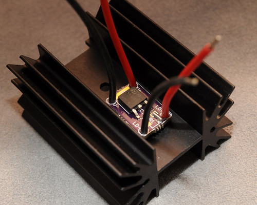
This driver is based on a LD1085 LDO regulator from ST Micro. Dropout is only 1.5V and can deliver 3A!

With 8V input and 4V load, I took it to 1.8A Iout before my bench PSU decided to shutdown (its max is 2A). It was cool to the touch. Ill try 2x26650 IMRs as soon as I find a suitable battery holder. This driver has 0.5ohm 4W set resistance for theoretical 2.5A.

Of course lots of heatsinking required:
 
This LM317 circuit is a great current regulator for diodes, but I would make 2 small changes that will solve the disconnected diode problem.

1. Replace the silicon diode with a zener diode (Digi-Key - MAZ40240LFCT-ND (Manufacturer - MAZ40240LF)). This will clamp the output voltage to no more than 2.4V (if you chose a different zener that voltage may change) and still provide protection against connecting the battery backwards. Connect the zener just like the silicon diode is shown, with the fat part of the triangle on the battery's negative and the point of the triangle connected to the LM317 adj pin.

2. Move the capacitor before the 4 ohm resistor, but after the pot. This way the resistor will protect the laser from the capacitor's full current output and the cap will still smooth out the battery voltage. Be careful here...if you connect a battery or power supply that is larger than the capacitors rated voltage and turn the pot all the way down you will blow the capacitor.

I hope this helps keep your laser diodes happy!
 
I probably don't understand this theory well enough to comment, but can I pose the potential problems I think I see? These may not actually be valid concerns:

1) Does this limit the laser diode's available voltage to 2.4V when running?

2) Given that the regulator works by trying to maintain 1.25V across the Out and Adj pins, would moving the capacitor between these two pins potentially impact upon the regulator's adjustment process ?
 
The zener is ininfluent, the silicon diode already protect against the battery reversal ..... and yes, any capacitor connected to adj pin (if the pin is not connected directly to the load) will slow down the regulation speed (anyway, for use as current regulator, where the adj pin is connected to the load, the problem is almost unexistent).
 
Was he trying to suggest that a zener diode could prevent the danger of a capacitor discharge killing the LD if someone forgot to discharge the cap? I wasn't quite understanding his intended purpose of using a different diode to begin with.
 
I probably don't understand this theory well enough to comment, but can I pose the potential problems I think I see? These may not actually be valid concerns:

1) Does this limit the laser diode's available voltage to 2.4V when running?

2) Given that the regulator works by trying to maintain 1.25V across the Out and Adj pins, would moving the capacitor between these two pins potentially impact upon the regulator's adjustment process ?

The answers to your questions are yes and no.

1. The LM317 tries to output a voltage on the Out pin that makes the voltage on the Adj pin equal to 1.25V. With the Adj pin connected directly to the laser the laser will never see more than 1.25V unless the LM317 is broken. So, using the LM317 with the 2.4V zener diode will limit you to 2.4V across the diode, but you'll never get there because the LM317 is already limiting you to 1.25V...

2. Since you are dealing with DC voltages the capacitor will charge up to a voltage somewhere in-between the Out pin and 1.25V. This voltage will vary depending on where your pot is set and if you're using a 4ohm resistor or something else. Regardless of the voltage the capacitor charges up to, the LM317 will vary the voltage on the Out pin so that the Adj pin sees 1.25V. This action happens regardless of where you place the capacitor.

Think of the capacitor as being a balloon. When you blow it up and hold a constant air pressure nothing happens. When the input pressure changes the balloon tries to spit some pressure out or stretch to take some in. Likewise when the voltage on a cap changes it takes some in or puts some back out. This action works to smooth out the voltage in a circuit, but it also slows down the changes in a circuit a tiny bit. The delay in this circuit is somewhere around 6 milliseconds. For comparison consider that the incandescent light bulbs around you are actually blinking at 60 Hz. That is 17 milliseconds.
 
1) No. With the ADJ pin connected to the laser diode (which IS how we do it), the LM317 continues to increase the current supplied to the diode until the voltage across ADJ and OUT equals 1.25V with the resistor in between.

At least that's my understanding of how this IC works as a current regulator. Certainly your notion that the LD is limited to 1.25V is completely wrong. We're constantly running these diodes at 5 or 6V from LM317s here.

You're definitely right...sorry about that. In this case the zener is a horrible addition, but you can still move the cap behind the fixed resistor. That will provide a minimum of protection against an overcharged cap discharging directly into the laser diode.
 
Now I've got a question :)

I'm building a 250mA driver for an expensive 635 tomorrow. I want to go DDL because I trust the circuit more than anything else. However, I don't have any LM317s on hand anymore (never use them these days), and the closest I have is its higher current big brother the LM338.

Any additional considerations I should have in mind?

I'm using 2x li-ions, and that's a bunch higher than the Vf + dropout, so there's no voltage issue. Just curious about whether this IC does anything funky on account of being able to handle higher currents (even though I'm running it at a fairly low current)
 
Status
Not open for further replies.


Back
Top