- Joined
- Aug 18, 2007
- Messages
- 114
- Points
- 0
OK
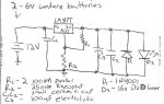
I have built my driver to the schematic, does it matter what voltage I use for the input (7v DC)?
And the higher the resistance on the pot the lesser the current to the diode right?
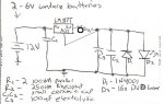
I have built my driver to the schematic, does it matter what voltage I use for the input (7v DC)?
And the higher the resistance on the pot the lesser the current to the diode right?


")