Welcome to Laser Pointer Forums - discuss green laser pointers, blue laser pointers, and all types of lasers

Buy Site Supporter Role (remove some ads) | LPF Donations

Links below open in new window

FrozenGate by Avery

DIY Homemade laser diode driver

Status
Not open for further replies.
Phenol --

Good point. You should have something like a 47 mfd electrolytic or a 10 mfd tantalum cap on the LD leads.

Mike


I think with 12v ur gonna get a very hot LM317T... unless im wrong.

also, 2 lantern batteries are big (lantern batteries are the BIG huge 6v rectangular prisms right?), I was thinking nice and portable, like AA sized 3v batts, or if u got the space rechargable 18650's. be careful with the litium crud, its dangerous, I'd suggest protected lithium batts. 6v shud be enough for a red ld.

dont make my mistake, I use 4 AAA batts, those sag very fast, and they are NiMH too!

and with the rheostat, I thought you had to connect 2 of the terminals together and put that on the vout, and the last terminal (of the three) goes to the adj. it loks like u got only 2 of the terminals used.

hope I can help, I'm not to good meself either

regards,

amk
 
Would it be alright to connect the 100mfd cap to the LD or does it need to be smaller. I need to go back to RS to get a perfboard to solder this all to, so I can pick up another cap then. The reason I added the small cap was because I read earlier that the larger electrolytic couldn't absorb high frequency noise.

I do have the Vout soldered to both terminals on the rheostat.

I'm not too worried about size for the moment. I'm using lantern batteries for now because I already have them and they're reliable. I'll go for something smaller when I can afford to. Isn't the 317 able to handle inputs up to 37V? I have mine heatsinked and I don't think it'll have a problem with 12 volts.

My dmm only measures to 200ma so I put 10 led's in parallel and cranked it up to about 196ma. The end resistance was around 6.1ohms. I'll be using this with a red LD from senkat when it arrives. What current should I be running through it? Is there a good current that will work for burning without decreasing the life of these diodes?
 
100 microfarads would be aright. it may be bigger in size than lower value caps, thought. if you have a ceramic cap /10n-100n/ at hand, you could solder it in parallel with the electrolytic one, at best - directly across the prongs of the LD.
concerning safe operating conditions of ur LD, they are a combination of junction temperature and current. it will probably burn from close distance at only 120mA thru it, it is rated for 80mW CW at 130mA and working Tj of 75C, yet, keeping it cool below that, it will withstand, based on the general experience here, 250mA if not more. it would be interesting to at least have a vague idea about its expected lifetime versus current at a fixed temperature. in general-the harder you push it, the hotter it gets, the shorter it lives. running too much current thru it, though, even momentarily, will result in COD
 
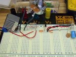
Size isn't an issue for me. I just want my first laser to work nicely. I found a small bag of 104M caps so I'll use those. The diode in the picture i pulled from a cd burner and won't be powering, I just put it in to show my complete circuit. I pulled the caps out of the breadboard and leaned them against the diode. The 100uf and .1uf caps I'll solder to the red LD when it comes.
 

Attachments

  • hpim0502rw8.jpg
    hpim0502rw8.jpg
    172.8 KB · Views: 416
anyone can rewrite this circuit for me for powering by a 4.5V battery source? thanks
 
I'm trying to understand all of this so eventually I can just go to the store, buy some parts and make a driver...

so I have a few questions.

What is the silicon diode? is that just the laser diode or is it something extra you need?

also, is it bad for a diode to have too much voltage pumping into it? why? what will happen?
 
The silicon diode is used for reverse polarity protection. Running the diode with too much voltage/current will kill it. The reason we regulate the current is so the current will remain the same going to the diode no matter what the input voltage is.
 
well i am reading daedal's guide as a guide for me, so this is where im getting all my information, just fiy.

so the silicon diode isn't really necessary if you are sure that you won't put the batteries in the wrong way?

also, the more volts you put in a circuit, does that also increase the current? I guess what I'm trying to ask is, why have a voltage regulator AND a current regulator?
 
Abray said:
well i am reading daedal's guide as a guide for me, so this is where im getting all my information, just fiy.

so the silicon diode isn't really necessary if you are sure that you won't put the batteries in the wrong way?

also, the more volts you put in a circuit, does that also increase the current? I guess what I'm trying to ask is, why have a voltage regulator AND a current regulator?

Abray,
The silicon diode isn't necessary.. you are correct about that. You only need a current regulator. The LM317 can be used as a voltage or current regulator, but when working with laser diodes we want to regulate the current. The same is true for those high powered LED flashlights. One of the reasons is as the laser diode heats up it tends to draw more current if using a voltage regulator. With a current regulator this will not happen.

The biggest drawback to the LM317 is its efficiency. You need to apply a minimum of 6 volts or more for the regulator to keep the current at its set range. 250ma's is fine with the SenKat diode or any 16X burner. Therefore I always recommend using 6 nimh batteries to power the circuit. If you go much above 9 volts, the thermal protection of the regulator will kick in, and the current will drop. So if you planned to use 12 volts the regulator would need to be heatsinked.

All you really need to keep this circuit simple is the LM317T, a 1/2 watt 5 ohm resistor, and the capacitor.

I have found the information at this webpage to be very helpful in understanding the 317.

http://users.pandora.be/davshomepage/current-source.htm
 
oh that helps ALOT!!

so your driver is the voltage regulating one, Gazoo?

there are still questions though... haha
first of all, the 1N4001 is the silicon diode, correct?
I guess one thing I still don't get is voltage. I understand about current, but how does voltage work in a circuit? too much voltage will kill a diode, but is that just because voltage directly relates with current? and how do you know how much voltage is safe? or will that just come naturally with how much current you are using.

and I know this sounds dumb, but where do you get the number for the starting current from? before all the resistors?
 
Abray said:
oh that helps ALOT!!

so your driver is the voltage regulating one, Gazoo?

there are still questions though... haha
first of all, the 1N4001 is the silicon diode, correct?
I guess one thing I still don't get is voltage. I understand about current, but how does voltage work in a circuit? too much voltage will kill a diode, but is that just because voltage directly relates with current? and how do you know how much voltage is safe? or will that just come naturally with how much current you are using.

and I know this sounds dumb, but where do you get the number for the starting current from? before all the resistors?

Yes, the 1N4001 is a silicon diode.

I said the 317 could be used as a voltage or current regulator. Everyone is using it as a current regulator. When working with laser diodes it is always best to think in terms the current being applied to the diode and not the voltage.

It all boils down to ohms law and how ohms law works with different circuits and components such as resistors and regulators. But with the LM317 it is all very simple because the LM317 has a reference voltage that stays constant and it is 1.25 volts.

The resistor needed is calculated by taking the reference voltage and dividing it my the milliamps you want to power the diode with. So 1.25/.250 = 5 ohms.

The following link will help you with ohms law ;)

http://www.the12volt.com/ohm/ohmslaw.asp
 
Gazoo said:
The biggest drawback to the LM317 is its efficiency. You need to apply a minimum of 6 volts or more for the regulator to keep the current at its set range. 250ma's is fine with the SenKat diode or any 16X burner. Therefore I always recommend using 6 nimh batteries to power the circuit.
(...)

Well, for my first DIY red I used 4 AA NiMH batteries and the SenKat (sony) diode lases fine, using the ddl circuit. Perhaps the voltage is on the low end of what's needed for lasing, but it works. I'd imagine if anything the diode would have a longer life when driven at lower voltages.
 
Thats not a good idea, it wont give nearly enough voltage, 4aa ni-mh wont even be 6v when fully charged, just use 6 of them and measure the current when you adjust it.

...lazer.... ;D ;D ;D
 
wooooooolazer said:
Thats not a good idea, it wont give nearly enough current, 4aa ni-mh wont even be 6v when fully charged, just use 6 of them and measure the current when you adjust it.

...lazer.... ;D ;D ;D

What are you talking about. AA nimh batteries have no trouble supplying 250mA (or more) of current. I did measure the current when I completed my pointer (to 225mA). 4 nimh batteries will not effect the current draw, the diode will just see less voltage than when using 6. If it works using 4 (and not 6) this is probably preferable.
 
Status
Not open for further replies.


Back
Top