Welcome to Laser Pointer Forums - discuss green laser pointers, blue laser pointers, and all types of lasers
How to Register on LPF | LPF Donations
Navigation
Install the app
How to install the app on iOS
Follow along with the video below to see how to install our site as a web app on your home screen.
Note: This feature may not be available in some browsers.
More options

You are using an out of date browser. It may not display this or other websites correctly.
You should upgrade or use an alternative browser.
You should upgrade or use an alternative browser.
DIY Homemade laser diode driver
- Thread starter Daedal
- Start date
- Status
- Not open for further replies.


As you increase the resistance of the potentiometer, less current is needed to maintain the 1.25V drop across the sense resistor. Ohm's Law.
I'd suggest you read through the entire thread. I know it's a long one, and there's a lot of repeated information in it, but there's gold buried in there.
I'd suggest you read through the entire thread. I know it's a long one, and there's a lot of repeated information in it, but there's gold buried in there.
DNMEBOY said:Hi, I am newly registered to this forum and have 2 questions.
First, I have built this driver for my laser diode. However I could not locate a 100 ohm pot.
I was able to locate a 1 k, a 1m, and a 400 something k. for the sake of seeing if I could even build something like this I made it with the 1k pot. When I connect an xmas bulb to the driver and power it on I turn the pot all the way up and theres a dim glow in the bulb, very dim. I turn the pot down and the light goes off. Does this mean that I have built the driver correctly and its working? I know I have the wrong pot and it wont power my diode but I need to know if this means my driver is functioning correctly. I think it is. Also I have the driver powered form a 7.4volt lipo battery pack form a team losi micro t. From what I understand as long as I input at least 6 volts to the driver the power output remains at 2.5volts. If this is correct it would be safe to use the 7.4 volt pack right?
Second question, My diode does not look like the one that came out of my aixiz housing. I assume its an open can. I can see right inside of the diode and see 2 pins and the laser in the center. I placed it in the housing and can somewhat focus the beam. This will still work right?
It is form a lite on it 20x dvd burner. I connected it to an old laser pointer and it lights up fine. its just not as bright as I would have expected.
So after reading this all that I should need now is the 100 ohm pot right? Is there a work around so I can make this work with out it? i have been waiting a very long time to build my burning laser and if I'm this close I am happy.
Thank you for your time in answering my questions.
I'm using a 1k pot from radioshack. You can use it, but it will be really sensitive to even a slightest movement.
set it then hot glue it so it won't move and kill your laser while running.
I am using this exact driver for my blu ray and i cant get more than 22mA into the diode. with the pot fully turned(least resistance) there is a total of 22mA going through the diode. With no diode in the circuit, it outputs about 239mA. Is something wrong here?
this is correct as for the leads i believe
this is correct as for the leads i believe
Attachments
busterhax said:I am using this exact driver for my blu ray and i cant get more than 22mA into the diode. with the pot fully turned(least resistance) there is a total of 22mA going through the diode. With no diode in the circuit, it outputs about 239mA. Is something wrong here?
this is correct as for the leads i believe
Testing a LM317 based constant current source without a load is meaningless.
Can you please post in the 'Help & Repairs' board a picture of your circuit, showing all connections? I'll meet you there.
a_pyro_is said:[quote author=busterhax link=1185701612/630#644 date=1197572538]I am using this exact driver for my blu ray and i cant get more than 22mA into the diode. with the pot fully turned(least resistance) there is a total of 22mA going through the diode. With no diode in the circuit, it outputs about 239mA. Is something wrong here?
this is correct as for the leads i believe
Testing a LM317 based constant current source without a load is meaningless.
Can you please post in the 'Help & Repairs' board a picture of your circuit, showing all connections? I'll meet you there.[/quote]
thanks man, thread here
http://www.laserpointerforums.com/forums/YaBB.pl?num=1197574740/0
rkcstr
0
- Joined
- Dec 1, 2007
- Messages
- 1,368
- Points
- 0
To all who PMed me previously, please send them again. I'll try to make sure I'll respond to those I remember later today.
To the actual post, I have been having some problems with my driver:
The reference voltage seems wacky. I've been testing it and can't get it to work properly.
My parts: NCP1117 regulator (pin for pin match to LM317 except LDO), 3.9ohm resistor, 100ohm pot, standard rectifier diode (1A 100V), 68uf 16V tantalum cap.
So when I use a 9VDC supply wall wart (or 9V battery) the ouput voltage is normal for a red diode (2.9v), but the output current (as measured with 1 ohm resistor in series with LD) is 130ma. The adjust resistance (pot + resistor) is set to 25ohms, which at a 1.25v reference voltage should be 50ma output. But, when measured across the Vout and Vadj pins of the reg, the reference voltage is 3.3v.
And, when I use a 4.5v source (3xAA), the voltage is about 2.3v and the current drops to 55ma. The measured reference voltage is 1.35v. This correlates fine with calculations, but why is the reference voltage off??
Anyone have any ideas on the problem? And I've checked the circuit over and over as well as for shorts. Any ideas would be great, I want to be sure it's working properly before I use it on my brand new Blu-ray diode from DDL ;D
phenol
0
- Joined
- Oct 30, 2007
- Messages
- 533
- Points
- 18
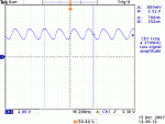
check with a scope Vout/Vadj for oscillations. remove the capacitor, connect a dummy load, and measure the values again. i experimented with a L1117 regulator which oscillated when there was a cap in parralel with the load. thats when it went straight to the junk box and i decided to stick firmly to op-amp-based sources.
phenol
0
- Joined
- Oct 30, 2007
- Messages
- 533
- Points
- 18
most basic DMMs wont measure beyond 20kHz. The oscillations I observed were DC-coupled, I didnt bother to measure their exact frequency, but it was well within the tens to hundreds kHz range and they were diminishing in amplitude as the regulator was heating up, but never stopped completely.
rog8811
0
- Joined
- Jul 24, 2007
- Messages
- 2,749
- Points
- 0
For the purposes of testing just remove the capacitor, if that cleans up your measurements phenol may have it right........
Regards rog8811
Regards rog8811
phenol said:most basic DMMs wont measure beyond 20kHz. The oscillations I observed were DC-coupled, I didnt bother to measure their exact frequency, but it was well within the tens to hundreds kHz range and they were diminishing in amplitude as the regulator was heating up, but never stopped completely.
I see
I'd have never figured the frequency to be that high.
rog8811 said:For the purposes of testing just remove the capacitor, if that cleans up your measurements phenol may have it right........
Regards rog8811
There you go again with the simple solution. ::sigh::
rkcstr
0
- Joined
- Dec 1, 2007
- Messages
- 1,368
- Points
- 0
a_pyro_is said:Please post a picture of your circuit showing all connections.
Also, let's get with Rog and delete our off-topic posts in his thread.
Pic in earlier post, but I'm attaching a circuit drawing.
phenol said:check with a scope Vout/Vadj for oscillations. remove the capacitor, connect a dummy load, and measure the values again. i experimented with a L1117 regulator which oscillated when there was a cap in parralel with the load. thats when it went straight to the junk box and i decided to stick firmly to op-amp-based sources.
Unfortunately I don't have a scope. But, according to the datasheet, for a current regulator circuit, there should be a low ESR cap from the output to ground, which the parallel cap in my circuit is.
I tried taking out the cap and the 9v output went up a small amount (both voltage and current), the 4.5v source Vref dropped in half (about .7v) along with the current output.
I tried putting a cap on the input, which didn't change anything. I tried removing the diode, which didn't change anything. What the hell?? Is this regulator just crap?
Attachments
phenol
0
- Joined
- Oct 30, 2007
- Messages
- 533
- Points
- 18
- Status
- Not open for further replies.


