Welcome to Laser Pointer Forums - discuss green laser pointers, blue laser pointers, and all types of lasers

LPF Donation via Stripe | LPF Donation - Other Methods

Links below open in new window

ArcticMyst Security by Avery

Desired Specification for a new Driver?

Joined
Sep 4, 2018
Messages
562
Points
63
Hi all - I started drafting a specification for a new driver last night but I came to the realisation that since I'm extremely new to Lasers and the LPF - I have absolutely no idea what people would actually want :)

So this is a "feature request" thread. What things from existing drivers are essential features, what other features would people like. I want to design something that's actually useful. Even if it's a redesign of something that's out there but generally unavailable, or something that's using obsolete components I'd happily dip my toes in.

If I end up designing something that people actually want to use I'll make up some panels of them and see if I can get a good price for PCBs and assembly of a small batch to send round to people for evaluation.

Things I'm specifically looking for guidance on:
  • Dimensions & mounting holes etc. (Circular/rectangular?)
  • Input & Output voltage range (Buck or Boost? Buck-boost?)
  • Protection (reverse polarity, undervoltage, thermal, any others?)
  • Kit form or assembled & tested?


Joined
Sep 20, 2013
Messages
17,253
Points
113
All drivers sold here are assembled and tested before they are sold. Astralist has been a member here who has supplied many of the new drivers we have had here. Lazeerer was a supplier of many high quality drivers to the LPF, but has been missing for over two years now. We try to get the smallest, but highest current regulating drivers that can be made as they often have to fit into small spaces. 11 mm by 10 mm is a typical size for all drivers regardless of topology. Many are boost or buck or boost/buck or sepic topology. Some are set current drivers while others are adjustable. Also being able to heat sink the driver inside a small space is always a plus. Hope this gives you an idea if you are wanting to do this here. As many have found, what you can design on paper doesn't always translate to a working driver, so prototype your drivers before going into production.
 
Last edited:
Joined
Sep 16, 2007
Messages
3,658
Points
113
Most of the drivers that have popped up since the Micro Flex V5 and Micro Boost drivers became unavailable were designed for the new generation of very powerful blue diodes that require >1 A @ 4-5 V.
However, these drivers aren't ideal for the new lower power diodes.
What is missing now is a boost driver capable of at least 7 V out from 3-4 V in and ~60-100mA out on the low end.

As Paul noted, 11mm wide rectangular is a good size and shape for general purpose builds as that size will fit inside the modules we regularly use.

Most of the popular diodes are case neutral or case negative. A few are case positive. That might be an additional consideration in the design parameters.
 
Last edited:

jnrpop

0
Joined
Dec 7, 2008
Messages
722
Points
63
Hi Immo1282, welcome :beer:

A few features that i would like would be:
- overvoltage and polarity protection
- A Low voltage warning, eg; strobing effect
- Open-circuit protection, eg; to prevent the loss of the boost driver in the case of loose/open connections to the load
- Slow ramp-up power on, eg; 2 seconds
- no conductive components/PCB/solder pads on the edges of the driver. To prevent shorting inside modules etc
- easy solder pads/holes for 22/24 awg silicone wire
- All pcb components on one side for easy heatsinking
- A Boost driver for 50mA-2000mA, 4 - 8V output
- A quality Potentiometer.
- Pre-assembled drivers with silicone Leads attached to both the input and diode connections.

Not to much to consider :crackup: Im sure ive forgotten a few things too :D

All the best for your design :beer:

J
 

Benm

0
Joined
Aug 16, 2007
Messages
7,896
Points
113
The topology demands will be variable of course - in some situations you clearly need to buck or boost, in some it may be required to be able to do both (i.e. when the forward voltage of your laser is lower than the start voltage of your battery, but higher than it's cut-off point).

One thing i could think of is a design where you can actually change the parameters by adjusting values in software. Change things like output current, max voltage, minimum input voltage to operate, ramp up speed on startup etc.

Such would allow a most flexible design, without any resistors to change around to adjust max current or anything like that.

To allow this you would need data access to the driver though, perhaps some JTAG or I2C interface. Having that on board would take quite some space, and bringing it to the outside of the case would be even more difficult.

Then again, how cool would it be to have a driver that you connect to with some pogo pins or something similar, and just change the settings in software for set current, thermal shutdown temperature or lowest acceptable battery life?

Perhaps it could even be contactless like using bluetooth, though that may be a bit difficult from within a metal enclosure and also be a safety risk.
 
Joined
Sep 4, 2018
Messages
562
Points
63
Thanks all - food for thought definitely.

Paul - Thanks for sharing your experience. I'd not necessarily planned to go into full production, more keeping to prototypes and small panel sizes to keep development costs down (this is a new hobby after all, not a way I think I can actually make money!). I think from what's out there I'd be better off trying to fill a niche than replicating what's come before. I will be thoroughly testing anything I make or have manufactured before it goes out of my hands, don't worry - Work has a fancy electronic test-load and other test gear I should be able to use after hours.

RA_pierce - Interesting to see this lack of lower powered boost driver out there - I'm leaning towards trying to fill a niche so I'll do some research in that direction I think! Also would work well for my own plans for future builds for my own collection.

jnrpop - Lots there to think about :p Not sure I can come up with a clever way to do strobing on under-voltage purely analog :thinking: I work in the design of digital power supplies but fitting a DSP with digital power that small in 11x15mm feels...tricky... :)
 
Joined
Sep 20, 2013
Messages
17,253
Points
113
I have some Pico Boost drivers from astralist that fill this niche. They can be set to deliver 50 mA up to 1000 mA at 7 volts Vf from a single Li-ion battery.
 

jnrpop

0
Joined
Dec 7, 2008
Messages
722
Points
63
The topology demands will be variable of course - in some situations you clearly need to buck or boost, in some it may be required to be able to do both (i.e. when the forward voltage of your laser is lower than the start voltage of your battery, but higher than it's cut-off point).

One thing i could think of is a design where you can actually change the parameters by adjusting values in software. Change things like output current, max voltage, minimum input voltage to operate, ramp up speed on startup etc.

Such would allow a most flexible design, without any resistors to change around to adjust max current or anything like that.

To allow this you would need data access to the driver though, perhaps some JTAG or I2C interface. Having that on board would take quite some space, and bringing it to the outside of the case would be even more difficult.

Then again, how cool would it be to have a driver that you connect to with some pogo pins or something similar, and just change the settings in software for set current, thermal shutdown temperature or lowest acceptable battery life?

Perhaps it could even be contactless like using bluetooth, though that may be a bit difficult from within a metal enclosure and also be a safety risk.

^ Incredible Idea, a fully programmable driver, also with headers for temp and other sensors, could be well suited for a Lab style build, but if small enough, im sure BBB would find a way to build it into a beautiful copper host :D
 
Joined
Jul 10, 2015
Messages
9,799
Points
113
Something I like is having the 8 pin chip in the clear so I can bond it to my heat sink, I have been using the artic alumina and it works well but having an easy place to bond too is desirable.

Also a higher available VF would be nice for running several diodes in series.
 

kecked

0
Joined
Jun 18, 2012
Messages
929
Points
63
Well this depends on what you intend. Paul described the needs for a laser pointer. I on the other hand I look from the projector side for graphics. From my persceptive and others have said this. There needs to be a selection below 500ma and above 1amp. And yes maybe one in the middle. Higher power needs to reach at least 5a. The fet or active element needs to be off board mounted for the higher power devices. A big problem is heat. Next the unit needs to be ground referenced for the diode so you don’t hsv3cto float it. What a pain the other way. You need soft start and a delay at turn on. Pretty much look at the old flexmod. Last if you want to addbeam suppression it needs to be selectable. No not last here is last. Th3 traces and pads need to be big enough for easy soldering and to handle the current. Crimp on connectors for diodes is asking for trouble. It will loosen at some point. I like the green ones you lock down with a screw. Size doesn’t matter to me. I left out 5he usual bias power adjust stuff. Well now it’s there.

You can’t make one driver suit all. I like to run off 12-24v. They want boost from 3-7 volts. Oh. Modulation must be analog and be able to make a square wave from a square wave up to 100khz. Same for anywaveform. Essentially this is a current amplifier.
 
Joined
Jul 10, 2015
Messages
9,799
Points
113
That's the truth of the matter, you can't have a 1 size fit's all, however I do like having an easy heat sink mounting point.
 
Joined
Dec 15, 2014
Messages
6,775
Points
113
Something I like is having the 8 pin chip in the clear so I can bond it to my heat sink, I have been using the artic alumina and it works well but having an easy place to bond too is desirable.

Also a higher available VF would be nice for running several diodes in series.


Hi,
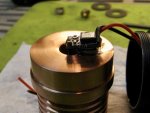
Yes 8 pin is good if I want extra hight I put a copper chip under the driver to raise it .

Rich:)
 

Attachments

  • fullsizeoutput_678.jpeg
    fullsizeoutput_678.jpeg
    118.5 KB · Views: 9

Benm

0
Joined
Aug 16, 2007
Messages
7,896
Points
113
I think the 'generic 8 pin chip' just refers to microcontrollers that are used in many devices, even just led decorative lights that can do various brightness amount or turn on for 6 hours a time and then off for the next 18 to keep repeating the cycle - this is the stuff you find in dollar store xmas lights.

It's quite feasible to find a suitable model though, preferably one with a built in thermal sensor, voltage reference and 2/3 ADC inputs so you can measure output current/voltage and battery voltage.

On the 8 pin variety you'd roughly use this:

- 2 pins for power supply/ground
- 3 pins for the ADC's
- 1 pin to drive the output trasistor/fet that switches the laser

One of the ADC input pins could see double use - you can use it for the power switch as well. If you want to track the battery voltage you may just pull that pin high with a switch to ground, and use the transition to ground to do the switching action.

I'm sure some chinese designer is doing exactly that at the moment, but if you could somehow make it in-circuit programmable that'd be great: we'd have our 8 pin mystery chip that's no longer a mystery at all and can be adjusted to our needs.

And yeah, you can use those ADC input's as serial lines for I2C or whatever as long as you provide a way to enter 'programming' mode - perhaps by powering the unit up while holding down the power button on it or something like that.
 
Joined
Sep 4, 2018
Messages
562
Points
63
Feature creep ! :eek:

Thanks for all the ideas. Going to go away and come up with a spec that's not ridiculous, prototype with something bigger then try and smoosh it down to pointer size. I'm not trying to make a 1-size fits all - I think more pointer oriented - but cramming all of those features into a 11x15mm board will be a challenge indeed.

From what you lot have said - it looks like a programmable digital solution is what's missing from the lineup. I'm going to put it out there and say that it's not straightforward to use a small (8 pin or otherwise) micro-controller that is fast enough to run the control loop for the buck/boost/buck-boost converter at the given size. At my day job, I am part of a team that's designing digitally controlled power converters that operate at around 100-200kHz switching frequency (and our development prototypes use fairly large microcontrollers) - much faster switching frequencies are required to keep the magnetic parts small in pointer driver boards from what I've seen. However a digital "supervisor" with a traditional analogue switching converter chip may be the ticket - with the processor providing the reference signals for a more standard tried-and-tested converter.

Going to sleep on it and see if it makes any more sense in the morning. Thanks again for the ideas!

-edit- Couldn't sleep so I did some research. Might stick to something purely analogue and straightforward at first - I like mini projects to have a visible endpoint at the moment. Don't want it to spiral out of control quite yet.
 
Last edited:

Benm

0
Joined
Aug 16, 2007
Messages
7,896
Points
113
Yeah, it's more than just a little function creep to realize this ;)

I think it can be done with relatively low cost, low power uC's however: If they run at 8 MHz and you're doing PWM at 100 kHz you have 80 clock cycles between any 2 transitions. This is probably sufficient to read a parameter (like output voltage) and make and adjustment for it... but it's not much code to run and you'd have to do that in assembler to get it to work.

If you want to have some button action you'd probably need to implement that as an interrupt, turning off the laser and executing whatever code is required to do the change state (say make it brighter or dimmer) and then resume to the assembly loop.

This is possible, but very complex to work out: if you actually want your uC to do the buck/boost driving you can't really have any interrupts on it unless you can turn off the output within in a few instructions. If you also want to do hardware key debouncing that'd mean turning off the laser for a fairly long period of time to check if something was a single press, double click etc.
 

rustynuts

Member
Joined
Dec 17, 2018
Messages
38
Points
8
Have you thought of adding suitable mounting holes so you can screw the board to a heat sink? or at least one mounting hole for the smallest PCB. If I were to design a PCB I would make the area around the mounting holes wide and be sure to keep any active traces at a good distance from any screws and spring washers.
A lot of Chinese designed PCBs have mounting holes, however all of them with poor trace routing ,Some traces touching the holes to save on space to save a penny. Also, I would advise that you dont use black or white solder mask colors. it makes seeing the traces inposable. This Is one reason why I hate working on apple boards. Oh, one last thought this is one reason why these colors are not used in medical boards, They need to be visually inspected .
 
Last edited:


Top