Welcome to Laser Pointer Forums - discuss green laser pointers, blue laser pointers, and all types of lasers

Buy Site Supporter Role (remove some ads) | LPF Donations

Links below open in new window

FrozenGate by Avery

DC-DC Buck Converter Design for 5V 5A laser control.

All I can say is that I already consider the diode that you will buy dead. Also, you don't need to compare anything, I have designed multiple actual drivers and there is so much that you have gotten wrong about everything that is not even funny anymore... But first I want to point out: you said that "LM311 turns on and off your diode" So I say look at your waveform:
unknown.png

I have marked the dead zones where the voltage of your converter drops to the 0 mark which is essentially turning off and on the diode. Then 40khz Is way way way too low, You will need a lot more output caps and also learn how to use a scope, To measure the ripple and get a proper waveform out of an SMPS converter you need to select AC coupling for your channel.... And finally, NOBODY HERE USES 311s FOR POWERING DIODES!
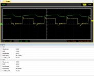
Giannis, that's the signal of the totem pole, it's not the signal of the buck converter. screenshotbuck50%.JPG
This is the signal of the step down, I already mention LM311 and LM317 just to point the difference vs DC-DC converters.


Cyparagon, Giannis_TDM, I assume that you program Arduinos, so that explain all.
We don't program Lol we just make stuff that works not based on general-purpose microcontrollers... Let's see if you can make a 7mm x 12.8mm 1A capable boost driver with a 3mv ripple reverse polarity protection and no diode killing features:
unknown.png

unknown.png

unknown.png

let's see how yours performs Mr PWM linear regulator.
 
Cyparagon, Giannis_TDM, I assume that you program Arduinos, so that explain all.

UecOF.jpg


I try not to brag, and programming has precisely nothing to do with analog circuitry design, but since YOU brought it up, I actually program and repair literal supercomputers. I'm at the NOAA/WCOSS-II installation as I type this. So go fuck yourself and learn some basic electronics before you tell an entire forum they're doing it wrong.
 
Someone has their little sentiments touched. Just wait foxs, and we gonna see, my CNC laser powered with STM32F7 will prove you what true mens are made of. BTW, you make my day with your comments.
 
What's the matter with all the people here? is this a twitter for electronics? I mean, it's ok the jokes and all that stuff, and I was providing ideas, that I already proved in reality, with facts based on books and experiments, and you... well. What I want to say is: that behavior is kind of stupid, you should go back to college and play with your freaking Arduinos.
 
Last edited:
What's the matter with all the people here? is this a twitter for electronics? I mean, it's ok the jokes and all that stuff, and I was providing ideas, that I already prove in reality, with facts based on books and experiments, and you... well. What I want to say is: that behavior is kind of stupid, you should go back to college and play with you freaking Arduinos.
Mate listen. We just pointed out why your design was unsuitable for laser diodes and what you needed to change calmly, We didn't try to offend you but you then continued with making stuck up statements on how we were wrong. You also seem to have a lacking knowledge in electronics, In case and point you said that the LM317, A linear regulator has a PWM output... Also, I would like you to show us how the circuit you posted the schematic of is in any way proven to work with real components and have a ripple of at least less than 100mv p-p and a current ripple of less than 20mA with an efficiency above 60%. If you cant to that take your offended ass back to elementary to learn why you can just follow an application circuit
on a book that is dated from the 80s and expect it to work for any application. Also don't act like you are above us for using the 2nd simplest IC series in the world to program lol wait till you get your hands on actual FPGAs
 
You miss understood what I was trying to say, if you supply an PWM to an LM it's obvious that you gonna have an PWM sigal output, that's why I used the step down, with that signal ripple I'm protecting the diode from the peak that you see if you use 1000uF F.E., if you believe that an totem pole is basic electronics, well, I respect your point. Actually I've a BASYS2 for some IFM range sensor laser projects, and I really want to share this with you guys, but this confirms what I already said, I'm not seeing a feedback based on books, white papers, IEEE documentation, TI or Fairchild documentation.

If I'm here is to improve myself and learn from you, and hey the loop is a good idea, LM317 is a good alternative, but if I learned something from college is that you cannot be at maximun with that kind of enviroment, and this forum has A LOT of that, NO ALL THE PEOPLE.
Ehm... The point is why supply a PWM signal to the lm at all? If you take your positive output from the adjust pin and tie it to the output pin via a resistor you essentially create a constant current feedback loop where I can be found using this formula: I= 1.25(V) : R(Ohms). There is no need to use a 317 with a PWM input. Then what do you mean? every regulated switching controller IC ever from Fairchild, TI, STM... Has a feedback loop in the circuit application because this is how they work. Also, let's give you some advice: If you base everything from stuff you learn at college and the shitty textbooks you get absolutely nowhere,
The circuit diagram you posted is an essentially unregulated switching converter that will not by itself limit current nor voltage. And laser diodes and generally all LEDs do not act like diodes, And because you don't seem to be listening to us do this experiment: Connect a high power LED to an amp meter and watch the current climbs at a set voltage as it heats up.
Please do not apply circuits that you saw in your textbooks once to the real world without them being fit to that specific use. LEDs and LDs need constant current regulated switching converters to work properly.
Just drop the SMT32 Idea, It's not fast enough. For good ripple and efficiency, you want something in the 600+Khz range. Go to TIs website and design something using their simple switcher series to get a basic grasp of what you need to do.(Note the Simple switcher series are intended to be a first step introduction to SMPS design so they are not really fit for driving laser diodes as their ripple commonly is above 80mv ish p-p even under perfect component values and they are CV not CC)

Edit: FYI the switching converter you posted can be used as a pre-regulator to just drop a voltage rail before it gets regulated by local fixed linear regs close to the chips who need power, This is how that circuit was used in the past and this is most likely the use that your books are referring to.
 
Last edited:
Ehm... The point is why supply a PWM signal to the lm at all? If you take your positive output from the adjust pin and tie it to the output pin via a resistor you essentially create a constant current feedback loop where I can be found using this formula: I= 1.25(V) : R(Ohms). There is no need to use a 317 with a PWM input. Then what do you mean? every regulated switching controller IC ever from Fairchild, TI, STM... Has a feedback loop in the circuit application because this is how they work. Also, let's give you some advice: If you base everything from stuff you learn at college and the shitty textbooks you get absolutely nowhere,
The circuit diagram you posted is an essentially unregulated switching converter that will not by itself limit current nor voltage. And laser diodes and generally all LEDs do not act like diodes, And because you don't seem to be listening to us do this experiment: Connect a high power LED to an amp meter and watch the current climbs at a set voltage as it heats up.
Please do not apply circuits that you saw in your textbooks once to the real world without them being fit to that specific use. LEDs and LDs need constant current regulated switching converters to work properly.
Just drop the SMT32 Idea, It's not fast enough. For good ripple and efficiency, you want something in the 600+Khz range. Go to TIs website and design something using their simple switcher series to get a basic grasp of what you need to do.(Note the Simple switcher series are intended to be a first step introduction to SMPS design so they are not really fit for driving laser diodes as their ripple commonly is above 80mv ish p-p even under perfect component values and they are CV not CC)

Edit: FYI the switching converter you posted can be used as a pre-regulator to just drop a voltage rail before it gets regulated by local fixed linear regs close to the chips who need power, This is how that circuit was used in the past and this is most likely the use that your books are referring to.
Hey, that's a good feedback, and already know it, but yes is good.


Back
Top