Welcome to Laser Pointer Forums - discuss green laser pointers, blue laser pointers, and all types of lasers

LPF Donation via Stripe | LPF Donation - Other Methods

Links below open in new window

ArcticMyst Security by Avery

Can you find out the polarity of a diode without datasheet?

Mannitu78

Member
Joined
Dec 19, 2019
Messages
92
Points
8
Hello men,
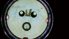
i just "found" these markings on my new Nichia NUBMOE 5,5w Laser diode..i never realized they were there until now. Do this lines, maybe, give information whats the anode and what is Cathode? I must say i still have troubles getting sure what the polarity is. The usual datasheets confuse me, because i cant make out which pin is 1 and 2, because i dont know with confidence from which side that picture shows the diode. Im still dependet on "idiotproof" pictures with the pins.

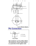
i will link a picture from a datasheet of the NBD7275,(didnt find any of my NUBMOE yet...), hoping i can clarify my difficulty and that someone can tell me if im right or wrong...
so in the middle picture, its said that the right pin is 2 and left pin is 1. The diode is placed in a way that the pins are at bottom, or, with other words, the side without "a small piece missing at the edge" is downwards. Now does that mean, if the diode is in front of me like that, the right pin is cathode(neg)??
Because in the bottom picture it is said, pin 2 is cathode. But in the bottom picture 2 is left and 1 is right. Now the picture does not look like the physical form of a diode but its still confusing me. :(


Attachments

  • WIN_20220120_20_33_27_Pro.jpg
    WIN_20220120_20_33_27_Pro.jpg
    202 KB · Views: 7
  • Unbenannt.PNG
    Unbenannt.PNG
    162 KB · Views: 7


Joined
Feb 4, 2010
Messages
3,280
Points
113
I have no idea what the lines are on your diode, but it's easy to follow the datasheet to find the pinout.

LD Reference.png

Edit: Always have your datasheets! Not trying to dodge your question on how to check without one, I just don't have a good answer for you.
 
Last edited:

Mannitu78

Member
Joined
Dec 19, 2019
Messages
92
Points
8
ok thank you...that was my first impression, right pin is neg. If you have the pins on the lower side. But the rest of datasheet confused me. Also i associated the longer line with cathode and shorter with anode...i thought that might be the meaning. Unfort., i still havent found the datasheet for my NUBM0E...only was able to find the one from the complete laserarray/bank, but not the single diode...im assuming its the same layout than the upper one but i hope ill manage to confirm that. Thats why i hoped the markings could give a help.


edit: ah yeah i also measured resistance on my diode, i had 7MegaOhm the one way and nothing/overload the other way...sure that would help me if i had a clue what to make of that reading XD
 

Attachments

  • Unbenannt.PNG
    Unbenannt.PNG
    407.2 KB · Views: 4

WizardG

0
LPF Site Supporter
Joined
May 9, 2011
Messages
1,189
Points
113
Ohm meter checks can be hazardous to 405 diodes. The reverse breakdown voltage of these diodes is lower than their forward operating voltage. Checking forward vs reverse resistance with a DMM can kill these diodes. You should be able to get away with it with longer wavelength diodes.
 

Mannitu78

Member
Joined
Dec 19, 2019
Messages
92
Points
8
well thanks thats good to know...seems ive been lucky this time, i just hooked it up and it works, man thats a wonderful diode..i set the driver to only about 600mA because i havent finished the modul yet and already its very bright
 
Joined
Dec 12, 2012
Messages
854
Points
63
Naturally, having the datasheet or pinout is preferable.
But if you apply a low voltage you can get some LED emission at lower current than threshold, a few times I've used that to confirm that my diode is hooked up correctly. As long as the voltage is below the reverse breakdown it should be OK. For it to be safe the led emission voltage would have to be lower than the maximum safe reverse voltage, and one might have to reverse polarity several time while raising the voltage? Not sure how safe that would be, but it might be an option when it is a completely unknown diode?
 

Mannitu78

Member
Joined
Dec 19, 2019
Messages
92
Points
8
well the markings must mean something theyre not there just like that?

edit:
@Mattronium?
reverse breakdown voltage? Is that always in the specsheet? cause it doesnt ring a bell. So what voltage do you mean, i can only hook 1 or 2 cells on the driver. Or do you mean hooking it on a naked battery?

PS:
can somebody give me a basic understanding what it needs to charge 2x16340 batteries? lets say i have them build into my host, but the host is difficult to open, so i want a way to charge them via USB while theyre inside the host. Can i just pull apart some USB cable, glue it to pos and neg of the battery stack, close the host and then charge them by USB? I think USB puts out 5V 1A. But i have no idea if thats it or you need some extra circuitry to charge the cells.
 
Last edited:

Mannitu78

Member
Joined
Dec 19, 2019
Messages
92
Points
8
so im an impatient noob so i just tested the version with USB cable...wow i never had so much Voltage on the battery, it tops at 4,22Volt usually. When i de-hooked the battery after 130min, it was very warm. Did i risk anything? Yeah i know im a noob XD
 

Attachments

  • DSCI1783[1].JPG
    DSCI1783[1].JPG
    787 KB · Views: 7
Joined
Dec 12, 2012
Messages
854
Points
63
well the markings must mean something theyre not there just like that?

edit:
@Mattronium?
reverse breakdown voltage? Is that always in the specsheet? cause it doesnt ring a bell. So what voltage do you mean, i can only hook 1 or 2 cells on the driver. Or do you mean hooking it on a naked battery?

PS:
can somebody give me a basic understanding what it needs to charge 2x16340 batteries? lets say i have them build into my host, but the host is difficult to open, so i want a way to charge them via USB while theyre inside the host. Can i just pull apart some USB cable, glue it to pos and neg of the battery stack, close the host and then charge them by USB? I think USB puts out 5V 1A. But i have no idea if thats it or you need some extra circuitry to charge the cells.

For what you are doing I would stick with reading the pinouts from the datasheets. That way there is no guesswork.

If you want to charge LI-ion batteries inside the host then more work will need to be done. Direct charging would be fairly dangerous if the voltage is not adequately regulated.
Charging must be done properly as improper charging can lead to damaging the batteries and possibly fires/explosion/battery damage. The first issue is that using two batteries complicates it a bit. I personally would use batteries that already have protection circuits on them, alternatively you can add protection circuits to the batteries, that would ensure that he batteries to not get charged to a dangerous voltage and provide additional protection. Then you would need a voltage source that is limited (regulated?) to 8.4V. Or you could integrate the voltage regulator inside the laser and use a more general external voltage source >9V probably. For most battery stuff there are purpose build components for it, so I'd look for those before trying to build it yourself.
If you can figure out a way to use removable batteries that would be ideal, if not then it will take more work and take some internet searching for answers.

The max charging voltage for Li-ions should be 4.2V I think it can go to 4.3V but any over that I don't think is safe. You most definitely should NOT be charging it with a 5V usb unless you have some form of voltage regulation to limit it to a safe voltage. I would suggest doing an ample amount of google searching for some of these questions to find answers for them. many here don't like answering simple questions.
 
Last edited:
Joined
Nov 2, 2012
Messages
626
Points
43
I remember "anode" and "cathode" like this:

Cathode "kicks off" electrons (the "c" sounds like "k" and "kathode" is the German spelling). To kick off electrons, the cathode must be negative.

Anode "accepts" electrons (both start with "a"). To accept electrons, the anode must be positive.

It helps me keep them straight, good luck.


Top